A hydraulic power unit reservoir is not just a container for oil. It supports fluid storage, return-flow management, air release, heat transfer, contamination control and service access. If the tank is chosen only by its outside dimensions or a convenient nominal volume, the power unit may be difficult to commission and harder to maintain.
This guide gives OEM engineers and equipment buyers a practical way to review reservoir requirements before requesting a hydraulic power unit quotation. It does not promote a universal tank-to-pump ratio. The correct design depends on the circuit, duty cycle, fluid, installation space and operating environment.
The reservoir should be defined after the hydraulic circuit has been understood. Begin with the actuators, valves, pump arrangement, operating sequence and expected return flow. A circuit that moves a cylinder intermittently has different reservoir requirements from a system that runs continuously or uses several actuators at once.
Collect the following information before selecting a tank:
This information turns “How many liters do we need?” into a more useful engineering question: how must the reservoir behave during the full operating cycle?
A tank's outside dimensions or nameplate volume do not tell the whole story. Part of the tank volume may be needed for expansion, return-flow calm-down, suction coverage and safe operating level. The usable operating volume is therefore different from the total geometric volume.
The design review should define:
- Normal oil level
- Minimum level for reliable pump suction
- Maximum filling level
- Space for thermal expansion
- Free volume for air release and return flow
- Drain and clean-out access
The pump should not draw from a level that allows air to enter the suction line. At the same time, the reservoir should not be filled so high that expansion or return agitation creates a secondary problem. Final levels must be set for the actual fluid and machine conditions.
Return oil can enter the reservoir with velocity, heat and entrained air. If the return port is too close to the suction outlet, the pump may receive poorly deaerated fluid before the tank has had time to separate air and calm the flow.
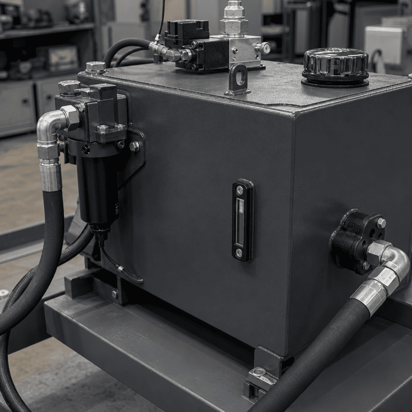
A sound layout considers:
The purpose is not simply to make the tank larger. It is to create a controlled path from return to suction so the fluid can release entrained air and settle before it is reused by the pump.
Pump suction deserves its own design check. The suction line should be short and direct where the installation allows, with a suitable diameter and a layout that avoids unnecessary restriction. Sharp changes in direction, poor inlet positioning or an undersized connection can create problems even when the nominal tank volume looks adequate.
Check the relationship between:
- Pump inlet location
- Minimum oil level
- Suction-line diameter and length
- Inlet strainer arrangement, if used
- Service access around the pump
- Tank drain and cleaning position
Do not select a suction arrangement only because it fits the enclosure. The pump manufacturer’s inlet requirements and the complete circuit conditions must be checked together.
The reservoir can help transfer heat to the surrounding environment, but it is not automatically a sufficient cooler. Heat generation depends on pressure losses, flow, cycle time, valve behavior, motor loading and the installation environment.
For an OEM review, record when the system produces heat and where the power unit will be installed. A compact enclosure near a heat source may need a different thermal solution from a ventilated unit installed in open air.
The correct sequence is:
1. Identify the operating duty.
2. Estimate where power is being lost.
3. Review the tank surface and air movement.
4. Decide whether additional cooling is required.
5. Verify the result during representative operation.
Avoid adding a cooler or increasing tank volume without understanding the actual source of heat. The reservoir is one part of the thermal design, not a substitute for circuit efficiency.
A reservoir design should make it difficult for dirt and water to enter and easy for maintenance staff to remove contamination. The filler-breather, access cover, drain point and return filtration arrangement all affect the cleanliness of the fluid.
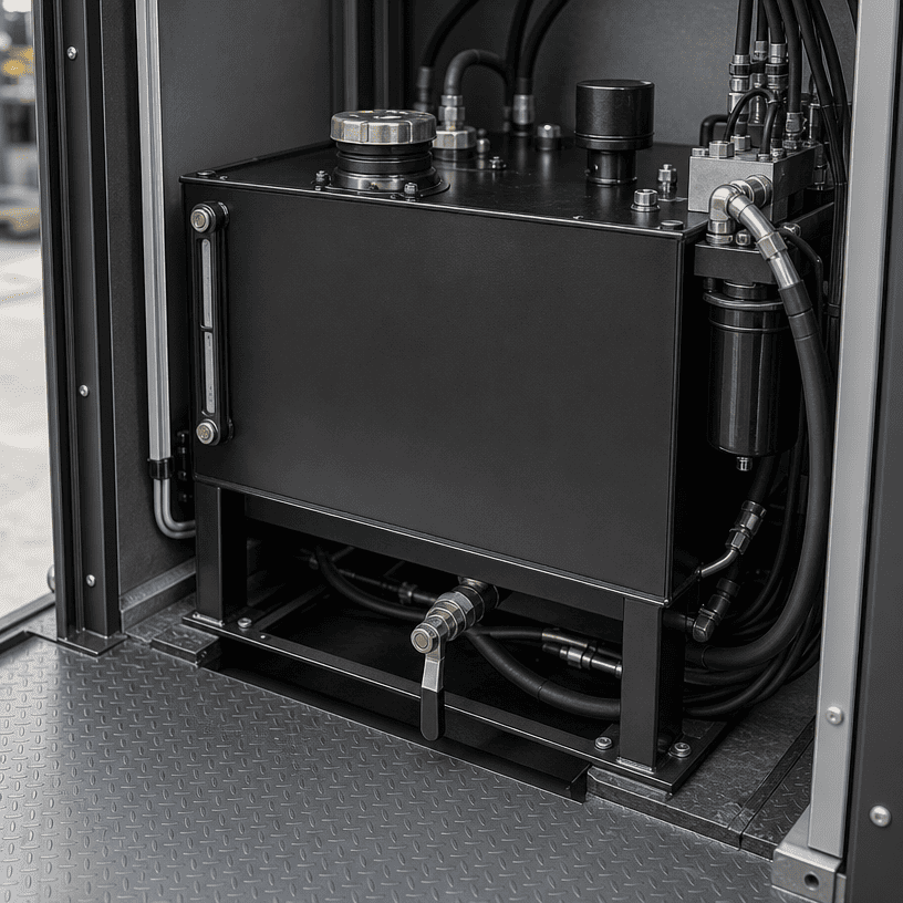
Useful design questions include:
- Is the filler opening protected from the surrounding environment?
- Can the breather be serviced without dismantling the power unit?
- Is the drain located at the lowest practical point?
- Can the tank be emptied without creating a spill hazard?
- Is the return filter accessible for inspection?
- Can the inside of the tank be cleaned when required?
The answer should be visible in the layout drawing. A clean-looking external enclosure does not prove that the internal maintenance path is practical.
Reservoirs often fail at the integration stage rather than the calculation stage. The tank may fit the nominal footprint but conflict with a motor, manifold, electrical enclosure, trailer frame, guarding or lifting point.
Before approving the design, review:
A three-dimensional layout or dimensioned assembly drawing can reveal conflicts earlier than a parts list. The reservoir must be serviceable after the power unit is installed, not only buildable on the workbench.
A useful quotation package normally includes:
If some values are not known, mark them as open items instead of filling them with assumptions. A transparent engineering review is faster than redesigning a tank after production has started.
Pump flow matters, but it does not describe the complete return pattern, duty cycle or actuator volume.
The tank needs defined minimum and maximum levels, expansion space and a controlled suction condition.
This can shorten the fluid path and reduce the opportunity for air release and flow calming.
A filler, breather, filter or drain that cannot be reached safely will eventually increase maintenance time.
Heat balance depends on the whole hydraulic circuit and installation environment.
The enclosure, pump, manifold, hoses and electrical parts need to be checked as one system.
Good hydraulic power unit reservoir sizing is a layout and operating-cycle exercise, not a volume guess. The engineer must review usable oil level, return-flow separation, pump suction, heat balance, contamination control and maintenance access together.
For a custom HPU project, send HCIC the circuit information and machine interface before the reservoir dimensions are finalized. That gives the design team a better basis for selecting the tank, pump, manifold, filtration and control arrangement as one integrated unit.
HCIC designs and manufactures hydraulic cylinders, hydraulic power units and related hydraulic systems for vehicle, industrial and engineering applications. HCIC's official power-unit resources show both standard catalog information and custom HPU support.
Website: https://jnhcic.com/
HPU product page: https://jnhcic.com/product/custom-hydraulic-power-unit/
Email: info@jnhcic.com