


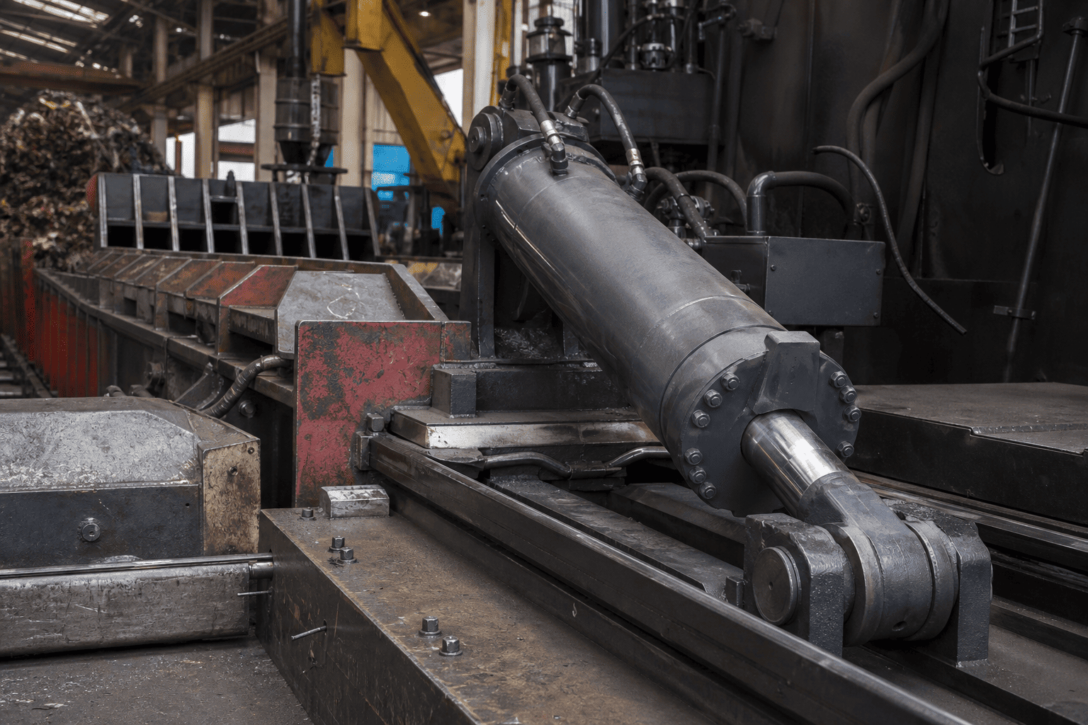
In high-cycle industrial and mobile equipment—including scrap metal balers, refuse compactors, timber processors, and automated forming presses—cycle time directly governs commercial profitability. Machine operators demand lightning-fast tool advance during the unloaded approach stroke, followed immediately by massive tonnage once the tool engages the workpiece.
Traditionally, achieving high extension speed required installing oversized hydraulic pumps, large displacement electric motors, and massive oil reservoirs. However, this brute-force approach introduces severe drawbacks:
A hydraulic cylinder regenerative circuit (often termed a differential circuit) eliminates this inefficiency. By routing the exhaust oil discharging from the rod end directly back into the piston blind end rather than dumping it to the reservoir, the cylinder reuses its own displaced fluid to accelerate extension speed by 150% to 250% without increasing pump displacement by a single cubic centimeter.
To understand how regenerative circuits achieve high speed, fluid power engineers examine the differential area between the hydraulic cylinder bore and the piston rod:
While regenerative circuits deliver outstanding speed benefits, improper valve selection or undersized cylinder ports cause severe operational failures in the field:
Because the fluid entering the cap end is significantly higher than the pump's rated output (often 2 to 3 times pump flow), standard cylinder ports become severe flow restrictions. High fluid velocity generates extreme turbulence, fluid shearing, and localized oil temperatures exceeding 100°C, causing rapid degradation of anti-wear additive packages and hardening of piston seals.
If an external counterbalance valve or restrictive directional control spool is incorrectly placed in the regenerative loop, returning oil cannot flow freely to the cap end. Trapped fluid in the annulus cavity experiences intense pressure multiplication, bulging the cylinder barrel, mushrooming the piston, or fracturing the rod gland threads.
Integrating regenerative circuits requires careful adherence to fluid power design rules:
| Circuit Component | Recommended Engineering Specification | Fatal Design Error to Avoid |
|---|---|---|
| Directional Control Valve | Oversized spool rated for 1.5× to 2.5× pump flow | Sizing spool strictly to pump flow (causes high backpressure & stalling) |
| Regenerative Selector Valve | Low-pressure-drop, pilot-operated logic element or PO check | Using direct-acting relief valves (causes severe flow throttling & heat) |
| Cylinder Port Sizing | SAE Code 61/62 4-Bolt Flange or oversized SAE ORB | Using small pipe threads (causes fluid shearing and port thread erosion) |
| Counterbalance Valving | Must be vented or placed outside the regenerative bypass | Trapping backpressure against the load holding valve (causes violent hunting) |
| Hydraulic Filtration | 10-micron absolute return-line filtration with visual bypass | Contamination jamming the high-speed regenerative shifting spool |
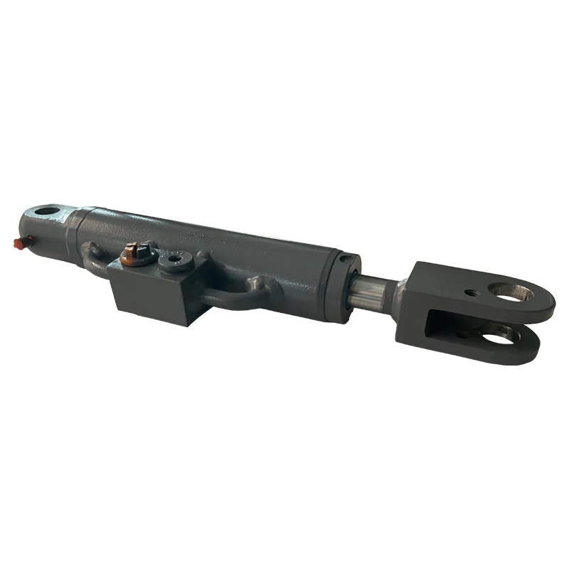
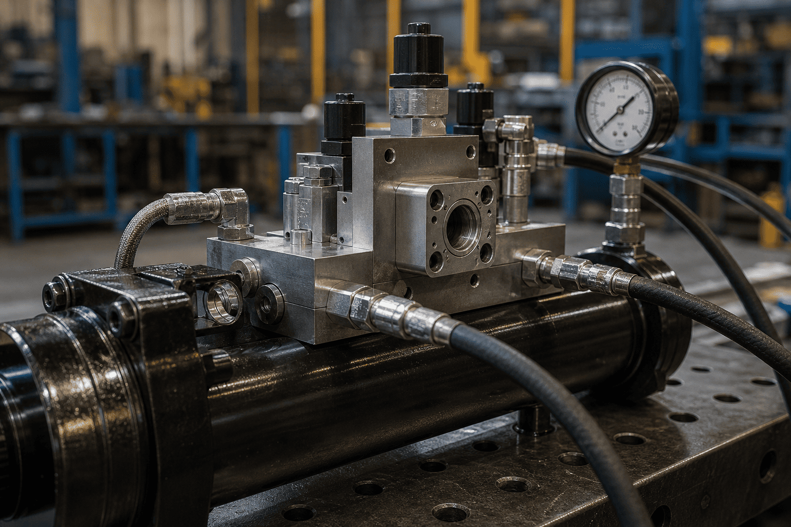
At HCIC, we design custom hydraulic cylinders with integrated regenerative manifold blocks mounted directly onto the cylinder barrel.
Zero External Plumbing: Manifold blocks bolted directly to the hydraulic cylinder eliminate failure-prone external steel tubing and high-pressure hose whips.
Optimized High-Flow Porting: Custom-machined oversized fluid passages maintain fluid velocity below, preventing oil overheating during 24/7 continuous operation.
Custom Pilot Valving: Factory-calibrated sequence cartridges ensure seamless, shock-free transition from rapid advance to full-tonnage crushing.