When a hydraulic cylinder fails to reach its designed cycle speed or runs scorching hot after thirty minutes of operation, engineers frequently blame the hydraulic pump or the directional control valve. In the workshop, however, the root cause is often far simpler: the cylinder ports and interconnecting plumbing are severely undersized for the required flow rate.
Fluid forced through a restricted port orifice behaves like water blasted through a pinched garden hose. Velocity skyrockets, laminar flow collapses into violent turbulence, and massive pressure drops develop across the port throat. This restriction converts valuable hydraulic horsepower directly into destructive heat, slows down rapid extension strokes, and can even trigger localized cavitation or back-pressure seal blowout during high-speed gravity retraction.
Getting your port sizing right is not just about matching whatever thread tap happens to be in the tool crib. It requires balancing fluid velocity across every operating line to ensure quiet, energy-efficient, and leak-free power delivery.
Fluid velocity dictates whether oil flows smoothly in parallel streamlines (laminar flow) or churns violently with high frictional resistance (turbulent flow). Industrial and mobile equipment builders follow strict velocity guidelines across different circuit branches:
| Circuit Branch / Line Type | Recommended Velocity (m/s) | Recommended Velocity (ft/s) |
|---|---|---|
| Pump Suction Lines | 0.5 to 1.2 m/s | 2.0 to 4.0 ft/s |
| Return Lines (Low Pressure) | 1.5 to 2.5 m/s | 5.0 to 8.0 ft/s |
| Continuous Pressure Lines | 3.0 to 5.0 m/s | 10.0 to 16.0 ft/s |
| Intermittent High-Flow Lines | Up to 6.0 m/s | Up to 20.0 ft/s (Short duty) |
| Cylinder Port Throats | 3.5 to 5.5 m/s | 12.0 to 18.0 ft/s |
In single-rod double-acting cylinders, oil exiting the cap end during retraction flow is multiplied by the area ratio (often 1.5:1 to 2:1). If a pump delivers 30 GPM into the rod cavity, **45 to 60 GPM surges out of the cap-end port. If the cap port was sized only for the 30 GPM supply rate, return line velocities can exceed 25 ft/s, creating massive back-pressure that fights the retraction stroke and overheats the entire system.
Use the following quick reference chart to select the minimum recommended cylinder port size based on instantaneous peak flow entering or exiting the port:
| Flow Rate (GPM) | Flow Rate (L/min) | SAE Straight ThreadO-Ring Boss (ORB) | SAE 4-Bolt Flange(Code 61 / Code 62) |
|---|---|---|---|
| 1 to 5 GPM | 4 to 19 L/min | SAE #4 (7/16-20) | Not Applicable |
| 5 to 12 GPM | 19 to 45 L/min | SAE #6 (9/16-18) | Not Applicable |
| 12 to 22 GPM | 45 to 83 L/min | SAE #8 (3/4-16) | 1/2" Code 61 Flange |
| 22 to 38 GPM | 83 to 144 L/min | SAE #10 (7/8-14) | 3/4" Code 61 Flange |
| 38 to 55 GPM | 144 to 208 L/min | SAE #12 (1-1/16-12) | 1" Code 61 Flange |
| 55 to 90 GPM | 208 to 340 L/min | SAE #16 (1-5/16-12) | 1-1/4" Code 61/62 |
| 90 to 150 GPM | 340 to 568 L/min | SAE #20 (1-5/8-12) | 1-1/2" Code 61/62 |
| 150+ GPM | 568+ L/min | Custom Manifold Block | 2" to 3" Code 62 |
[ SAE ORB (O-Ring Boss) ] ===> Zero-leak radial elastomeric seal; preferred for up to 5,000 psi
[ SAE 4-Bolt Flange ] ===> Heavy shock & vibration resistant; best for >1" high-flow ports
[ BSPP (G-Thread) ] ===> Bonded seal ring flat face; global ISO standard outside N. America
[ NPTF (Tapered Pipe) ] ===> Metal-to-metal wedging; prone to stress cracking and high-pressure leaks
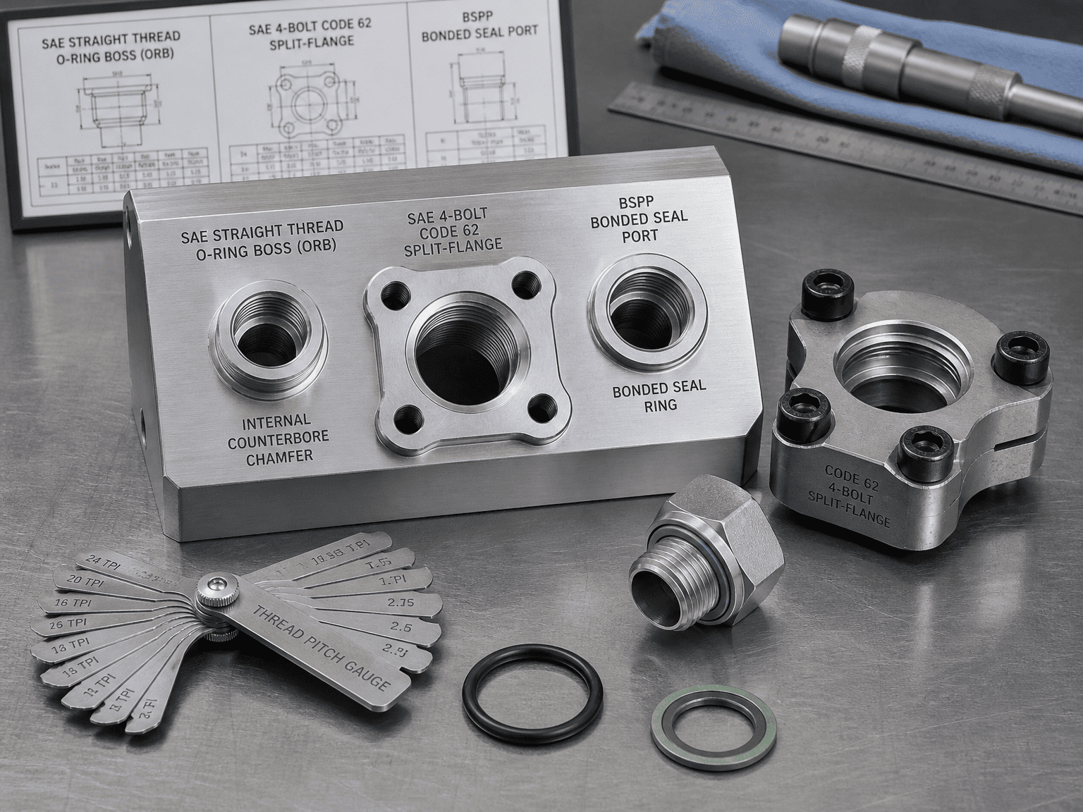
How it seals: Straight UN/UNF parallel threads provide mechanical clamping force, while an elastomeric O-ring seats into an internal machined counterbore chamfer.
Why OEMs prefer it: It eliminates the risk of overtightening cracks, allows adjustable 90-degree elbow orientation with locknuts, and reliably holds pressures up to 5,000 psi (345 bar) without weeping.
How it seals: A heavy split-flange or captive flange clamps a flat flange head containing a face O-ring directly against the hydraulic cylinder body with four high-tensile grade 8 bolts.
Best applications: Essential for port sizes 1-inch and larger on heavy mining excavators, large-tonnage scrap balers, and mobile cranes. It withstands intense mechanical line pulsing and allows compact line hookups without wrench swing interference.
How it seals: Parallel threads with an elastomeric bonded seal ring (Dowty washer) or retained O-ring against a spot-faced flat surface.
Best applications: The dominant international standard for European, Asian, and export commercial equipment, offering reliable zero-leak sealing equivalent to SAE ORB.
The failure mode: Tapered pipe threads rely on metal deformation along the thread flank. Under thermal expansion, pressure surges, and vibration, pipe dope washes away, causing leaks. Overtightening tapered fittings wedges the port boss outward, frequently splitting welded cylinder end caps.
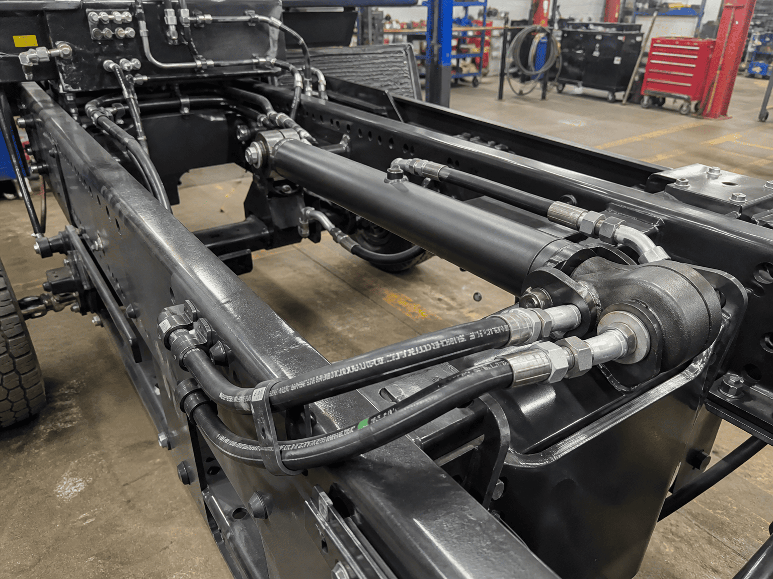
Even if your port thread size matches the flow chart, internal geometry flaws can still throttle your cylinder:
Velocity and port sizing recommendations in this guide represent industry-standard engineering best practices. For applications involving high-frequency servo cycling, water-glycol fluids, or severe duty cycles, consult HCIC engineering specialists for full computational fluid dynamics (CFD) and manifold optimization.
HCIC engineers high-performance custom hydraulic cylinders, integrated manifold blocks, and hydraulic power units for mobile and industrial equipment builders worldwide.