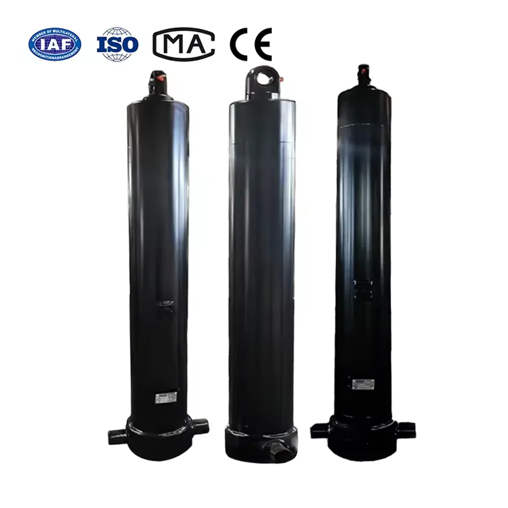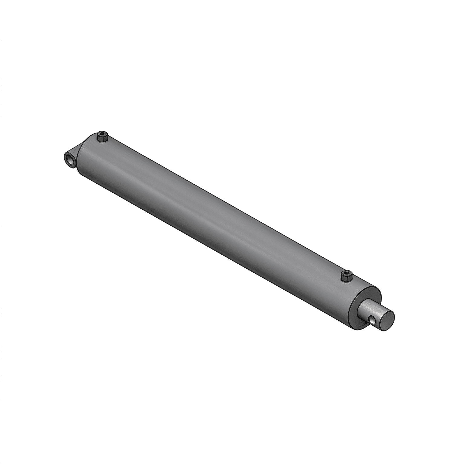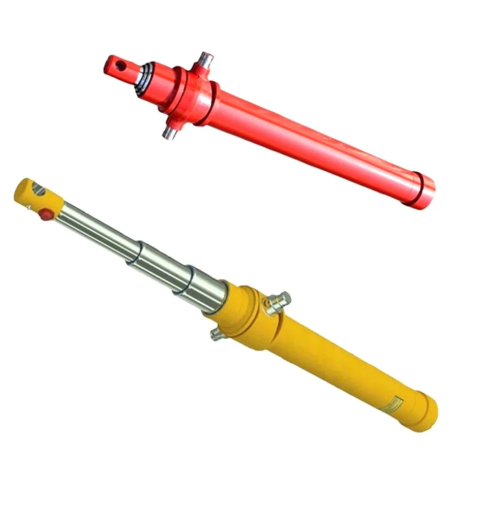
When a loaded boom or bucket hydraulic cylinder drops without operator input, the malfunction stems from one of four distinct hydraulic mechanisms:
| Failure Mechanism | Physical Root Cause | Audible / Visual Symptom |
|---|---|---|
| Piston Seal Bypass(Internal Leakage) | Extruded U-cup or scored wear rings leaking oil from cap end to rod end | Cylinder barrel hot spot; drift stops when rod is mechanically supported |
| Counterbalance ValveSeat Weeping | Contamination under poppet seat, scored cartridge nose, or fatigued spring | Oil weeping past valve port; steady drift regardless of seal condition |
| Directional ValveSpool Leakage | Excessive spool clearance wear in open-center systems | Only occurs if no lock valve is installed in the boom circuit |
| Thermal OilContraction | Hot oil (65°C) cooling to ambient (15°C) shrinks fluid volume by 3% to 4% | Initial 10-20 mm drop over first hour, then completely stabilizes with zero pressure loss |
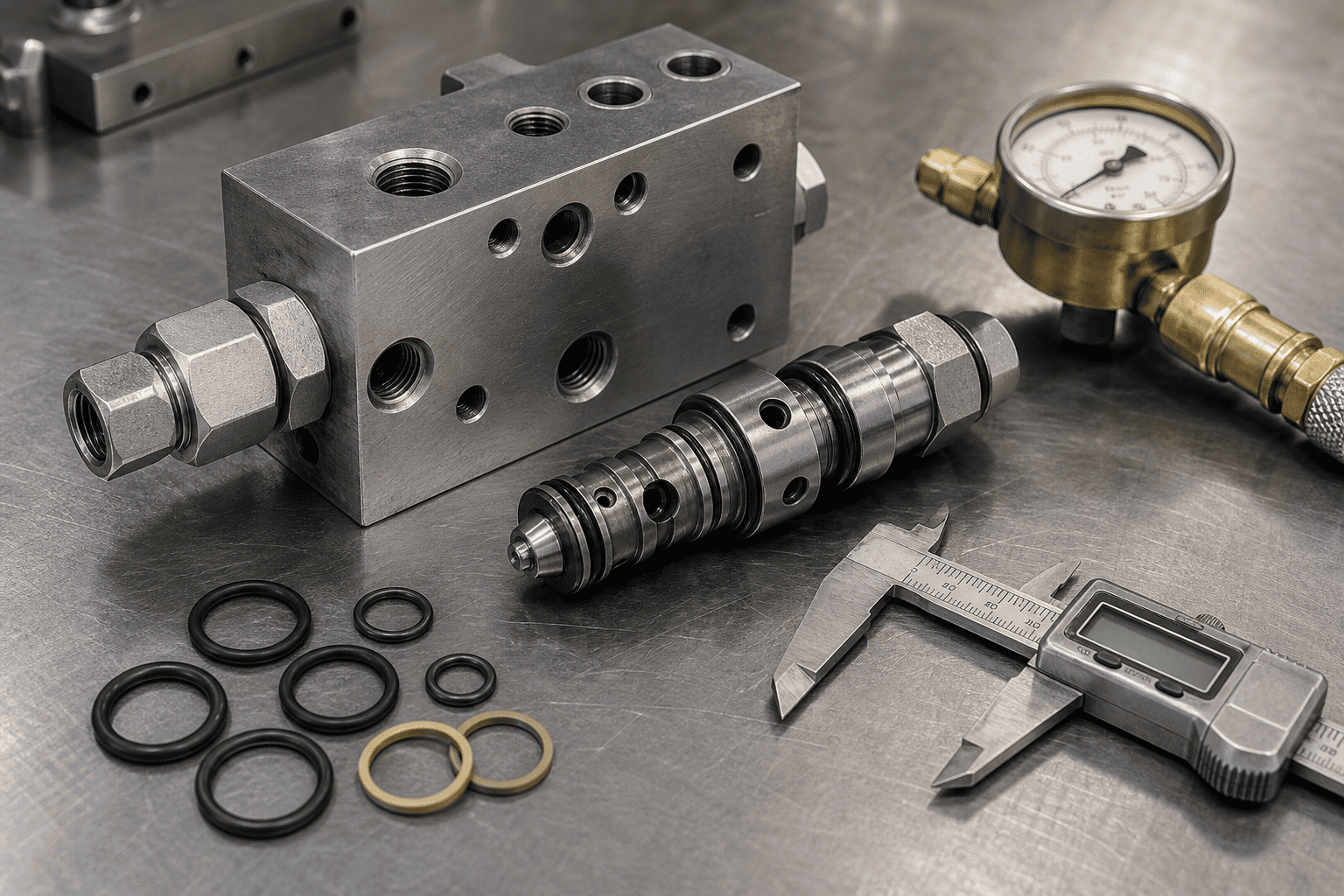
Never remove a heavy boom cylinder from a machine before completing this definitive isolation test:
1. Elevate Boom to 45 Degrees with Rated Load: Bring hydraulic oil up to normal operating temperature (approximately 50°C to 55°C).
2. Lock Out and Support the Boom Mechanically: Install an engineering-approved boom prop or crane sling to ensure absolute safety.
3. Isolate the Rod-End Return Line: Disconnect the hydraulic hose connected to the rod end (annular side) of the cylinder and cap the hose. Leave the cylinder rod-end port open over a clean measuring container.
4. Remove the Mechanical Support: Allow full gravity load to hang on the cylinder's cap-end oil column.
5. Observe Rod-End Port Discharge:
Counterbalance valves (overcenter valves) perform two critical duties: they trap oil to prevent load drop if a line bursts, and they meter return flow so overrunning gravity loads cannot outrun the hydraulic pump.
When an operator lowers a heavy boom and the machine begins violently bucking and chattering, the counterbalance valve is caught in pilot pressure instability (hunting):
| Step | Process Description |
|---|---|
| 1 | Operator sends lower command → Pilot pressure opens the counterbalance valve |
| 2 | Valve opens → Oil rushes out from cylinder cap end → Boom accelerates downward |
| 3 | Boom falls faster than pump can supply oil → Pilot pressure drops to zero |
| 4 | Pilot pressure loss → Valve suddenly slams shut → Hydraulic shock wave, boom shaking |
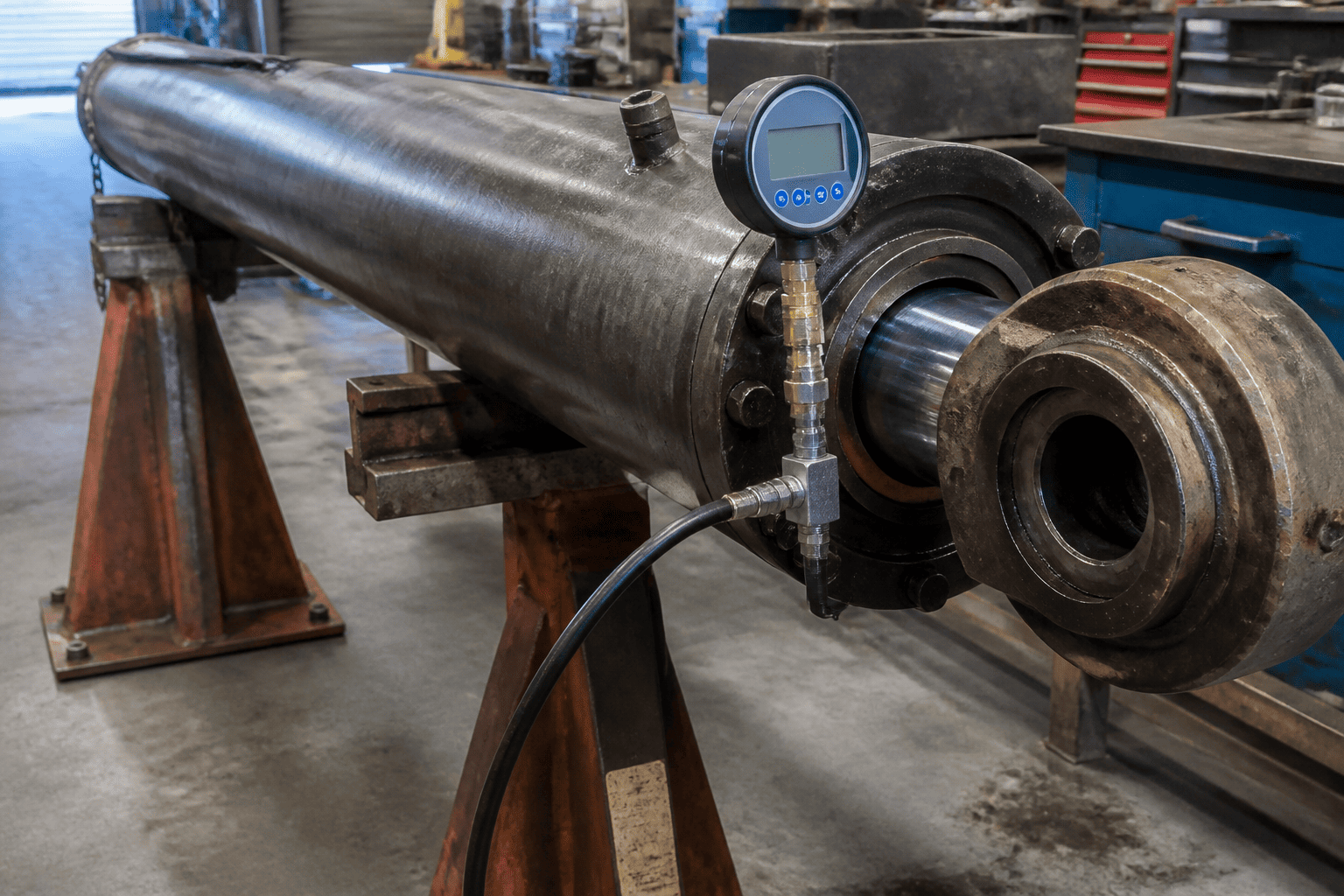
The primary engineering mistake that triggers counterbalance hunting is selecting an excessively aggressive pilot ratio for a flexible, structural boom:
1. Flush Counterbalance Cavities Before Torqueing: Even a 20-micron steel chip caught between the poppet nose and manifold seat will cause 50 mm of boom drift per hour. Always flush manifold drillings to ISO 16/14/11 cleanliness standards.
2. Specify Viton/HNBR Backup Rings for High-Pressure Holding: Ensure piston seal packages utilize anti-extrusion thermoplastic backup rings capable of withstanding 4,000+ psi continuous static holding without micro-creeping.
3. Differentiate Thermal Contraction from Real Leaks: When testing newly parked machinery, allow thirty minutes for oil temperature stabilization before recording drift benchmarks.
4. Install Direct-Flanged Counterbalance Manifolds: Avoid remote line-mounted valves. Bolting the valve block directly to SAE 4-bolt flange ports on the cylinder barrel ensures rigid pilot feedback and zero risk of external hose rupture.
Experiencing persistent boom drift or counterbalance valve instability across your equipment fleet?
Contact HCIC’s senior hydraulic engineering group. We provide complete forensic circuit reviews, custom-manifold integrated cylinders with optimized pilot ratios, and rapid-dispatch OEM replacement units engineered for zero-drift performance.