When field technicians suspect internal piston seal failure, the standard shop test is to bottom out the cylinder at full stroke, pressurize the port, and inspect the opposite port for oil weepage. In ballooned cylinders, this test consistently produces false-negative results:
| Position | Distance | Bore Measurement | Note |
|---|---|---|---|
| Base Cap | 0 mm | 100.02 mm | Nominal Spec |
| Mid-Stroke | 500 mm | 100.48 mm | +0.46 mm Swell Zone |
| Head Gland | 1000 mm | 100.03 mm | Nominal Spec |
Because the hydraulic cylinder barrel is structurally braced at both ends by the heavy steel base forging and the threaded head gland, permanent hoop yielding concentrates almost exclusively in the unsupported center section of the barrel.
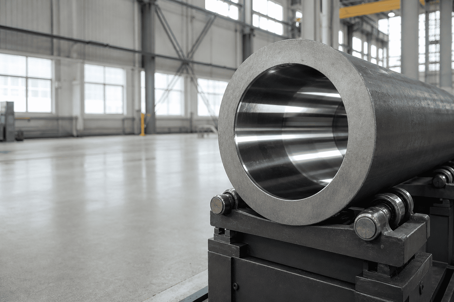
1. Inertial Kinetic Impact Spikes: An excavator bucket striking granite at full swing speed causes an instantaneous deceleration pressure spike that surges past system main relief valve crack limits before the valve poppet can physically shift open.
2. Decompression Shock Waves: In high-tonnage hydraulic presses and compaction cylinders, rapid valve shifting unleashes acoustic fluid decompression waves that hammer the internal tube ID.
3. Substandard Tube Metallurgy: Utilizing standard commercial cold-drawn carbon steel tubing with a low yield strength (under 350 MPa) instead of high-tensile alloy steel (over 520 MPa yield).
4. Excessive Tube Honing Allowance: Over-honing an already worn cylinder tube to remove deep scoring marks reduces the remaining tube wall thickness below minimum engineering safety margins.
To conclusively diagnose barrel ballooning during shop teardowns, mechanics must map the internal bore geometry across multiple stroke intervals rather than measuring only the easily accessible tube ends:
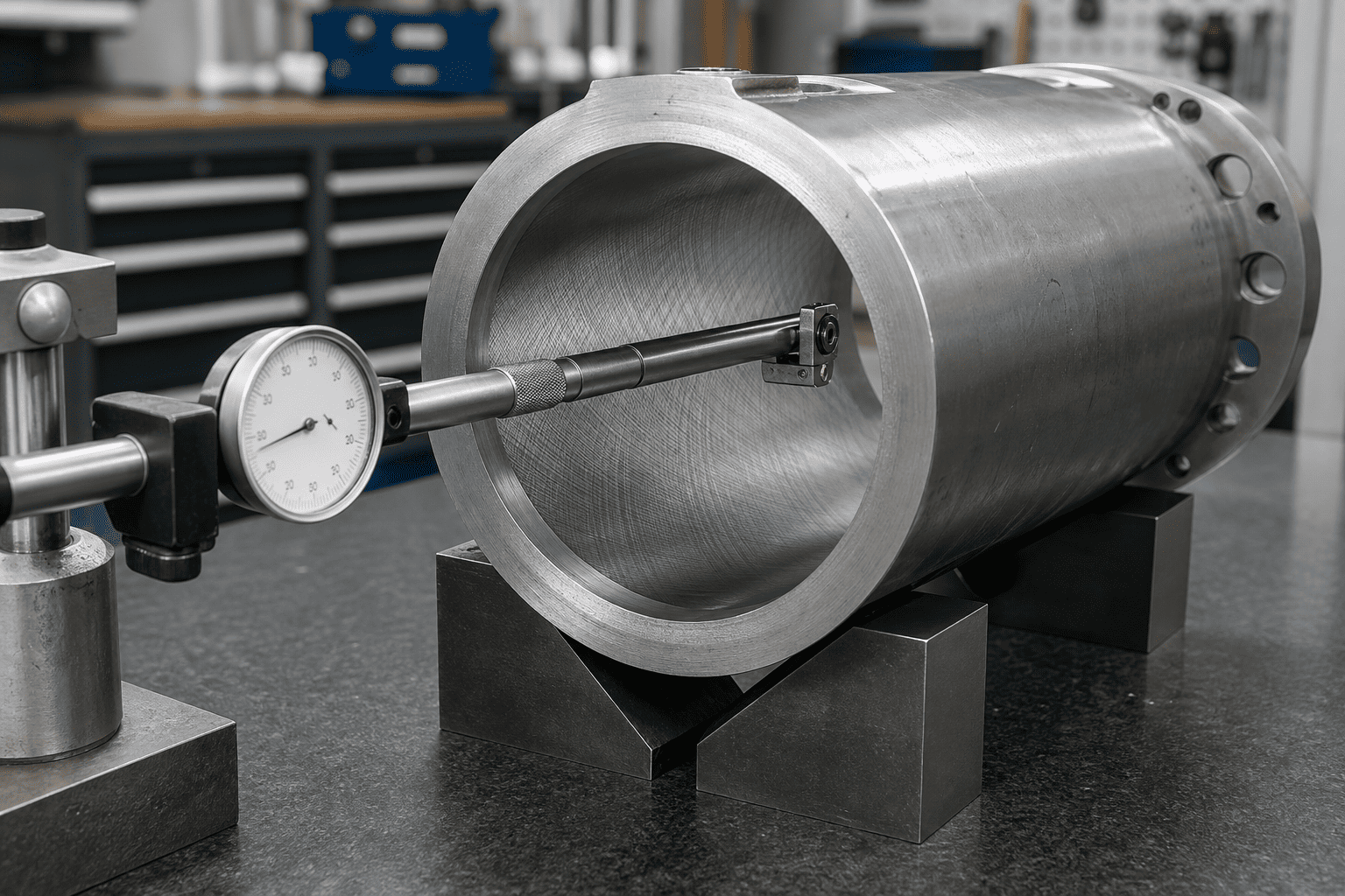
| Position | Distance | Bore Measurement | Note |
|---|---|---|---|
| Base Cap | 0 mm | 100.02 mm | Nominal Spec |
| Mid-Stroke | 500 mm | 100.48 mm | +0.46 mm Swell Zone |
| Head Gland | 1000 mm | 100.03 mm | Nominal Spec |
Preventing barrel ballooning in high-shock hydraulic circuits requires upgrading from standard carbon DOM tubing to high-strength seamless alloy steels:
| Tubing Grade | Material Classification | Minimum Yield Strength | Resistance to Peak Shock Spikes |
|---|---|---|---|
| AISI 1020 / 1026 | Standard Cold-Drawn Carbon | 290 – 340 MPa | Poor (prone to ballooning under 4,000 psi spikes) |
| St52-3 / E355 | Micro-Alloyed Structural Steel | 450 – 520 MPa | Moderate (standard mobile industrial benchmark) |
| 27SiMn / 30CrMo | Quenched & Tempered Alloy Steel | 620 – 780 MPa | Superior (resists 8,000+ psi dynamic mining shocks) |
| 4140 Chrome-Moly | High-Hardness Alloy Steel | 850 – 950 MPa | Extreme Duty (demolition attachments & forge presses) |
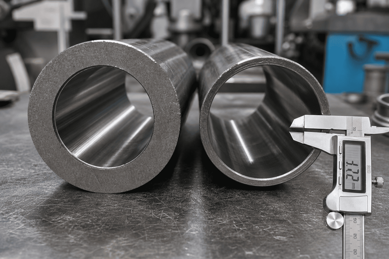
In addition to high-yield alloy selection, heavy-duty engineering guidelines require specifying heavy-wall ratios where the tube outer diameter is at least 1.25 to 1.35 times the nominal bore diameter in high-impact mobile equipment.
Dealing with unexplained mid-stroke loss of breakout force or barrel swelling in severe-duty equipment?
Consult with HCIC’s specialized hydraulic design engineering team. We supply heavy-wall, high-yield alloy cylinder assemblies engineered with certified 27SiMn/4140 seamless tubing, precision skived-and-burnished bores, and comprehensive CAD verification for severe-duty mobile and industrial machinery worldwide.