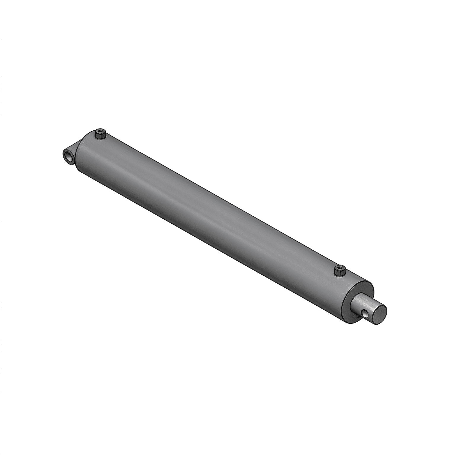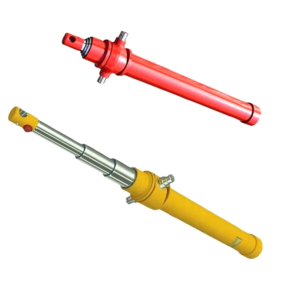
Few things frustrate a heavy equipment maintenance crew more than a boom or dump cylinder that suddenly starts chattering, moving with an erratic spongy lag, and making a loud rattling sound like a fistful of marbles tumbling through the steel tubing.
When mechanics tear the cylinder down, they expect to find dirty oil or a torn seal. Instead, they find the solid steel face of the piston crown and the inner lips of the oil ports peppered with rough, frosted craters that look like they were blasted with miniature buckshot.
This is not abrasive particle wear. It is hydraulic cylinder cavitation and aeration—two closely related but fundamentally distinct fluid phenomena that destroy precision metal surfaces, cook elastomer seals, and compromise machine safety.
In field service reports, technicians frequently lump cavitation and aeration together under the generic label of "air in the lines." Understanding how each happens is essential for fixing the true root cause:
Cavitation occurs when the demand for oil on one side of the hydraulic cylinder piston outpaces the rate at which oil can physically enter.
Aeration is the contamination of hydraulic oil with free atmospheric air pulled into the circuit from the outside environment.
| Diagnostic Check | Cavitation | Aeration |
|---|---|---|
| Audible Signature | Sharp, harsh rattling or grinding noise (like loose gravel or marbles rattling inside the cylinder barrel or valve block). | High-pitched whining or groaning buzz that gets louder as oil warms up. |
| Motion Quality | Hesitation during initial direction change followed by abrupt lurching under load. | Continuous spongy, springy, or bouncy cylinder extension; drift under static load. |
| Fluid Appearance | Oil sample looks clear in the tank, but components exhibit localized pitting. | Oil sample inside the sight glass looks milky, foamy, or cloudy with visible froth. |
| Operating Temperature | Severe localized hot spots on valve blocks or cylinder port elbows. | Rapid overheating of the entire reservoir tank due to continuous air compression. |
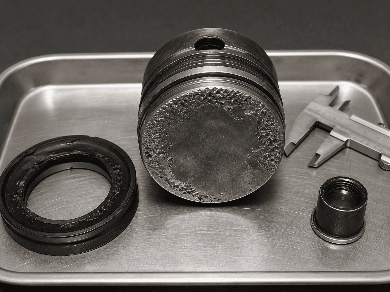
When fluid power systems suffer from chronic cavitation and aeration, physical damage concentrates in specific high-velocity zones:
4.1 Piston Crown Faces: The flat circular face of the piston exhibits clusters of deep, frosted micro-pits where collapsing vapor voids repeatedly struck the base metal.
4.2 Oil Port Internal Orifices: Sharp right-angle transitions where hydraulic oil enters the cylinder barrel suffer severe edge erosion and rounding.
4.3 Piston Rod Seals and Wear Rings: Entrained air bubbles undergo rapid adiabatic compression, creating localized heat spikes that scorch, glaze, and turn flexible polyurethane seal lips into brittle charcoal-like flakes.
4.4 Cylinder Barrel Honed Walls: Near the stroke extremes, micro-jets strip the protective lubricating oil film, allowing direct metal-to-metal scuffing between the piston guide bands and the polished tube bore.
When a heavy excavator boom, dump trailer body, or forklift mast descends rapidly under its own weight, gravity pulls the cylinder rod down faster than the hydraulic pump can supply oil to the cap side. The cylinder becomes a giant syringe, creating an intense internal vacuum that boils the incoming oil stream.
Thick, high-viscosity cold hydraulic oil struggles to flow through narrow suction strainers and long supply hoses. When an operator revs the engine to full throttle immediately after startup, the pump starves, pulling a heavy vacuum and sending a stream of cavitating fluid straight to the actuators.
As long-stroke cylinders extend, the fluid level inside the hydraulic tank drops significantly. If the tank breather cap is caked with mud, dust, or ice, atmospheric air cannot enter to equalize the volume. A partial vacuum develops inside the tank, choking the pump suction line.
If return oil plunges into the reservoir above the liquid level like a waterfall, it whips air into the oil. Without adequate tank baffles to let air bubbles rise to the surface and vent, the pump immediately sucks this foamy mixture back into the cylinders.
Fixing cylinder cavitation requires addressing the circuit dynamics that allow negative pressure to form:

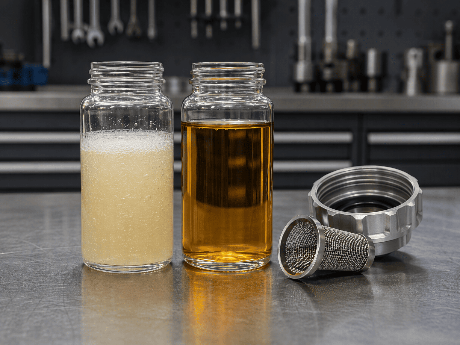
Before replacing a noisy or damaged cylinder:
This guide outlines standard mechanical diagnostic indicators and hydraulic circuit best practices. Complex multi-axis machinery, load-sensing variable displacement circuits, and closed-loop hydrostatic drives require circuit-specific transient pressure logging and fluid analysis to isolate root causes.*
HCIC designs and builds heavy-duty custom hydraulic cylinders with optimized port geometry, high-flow internal galleries, and integrated counterbalance valves to withstand severe duty cycles.