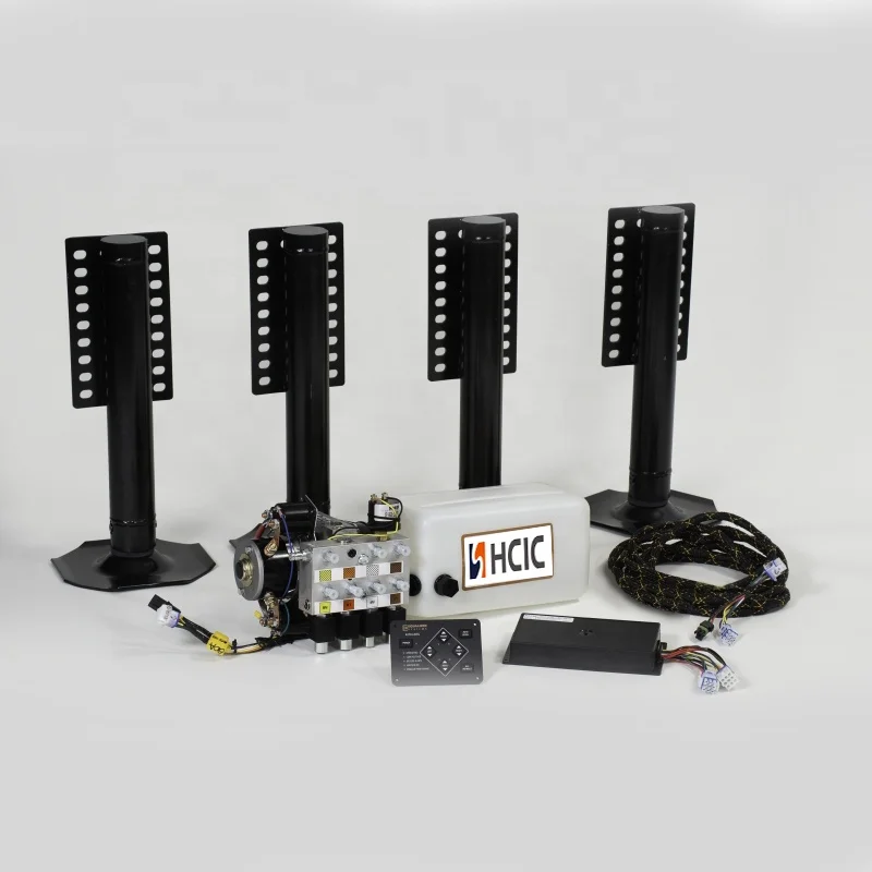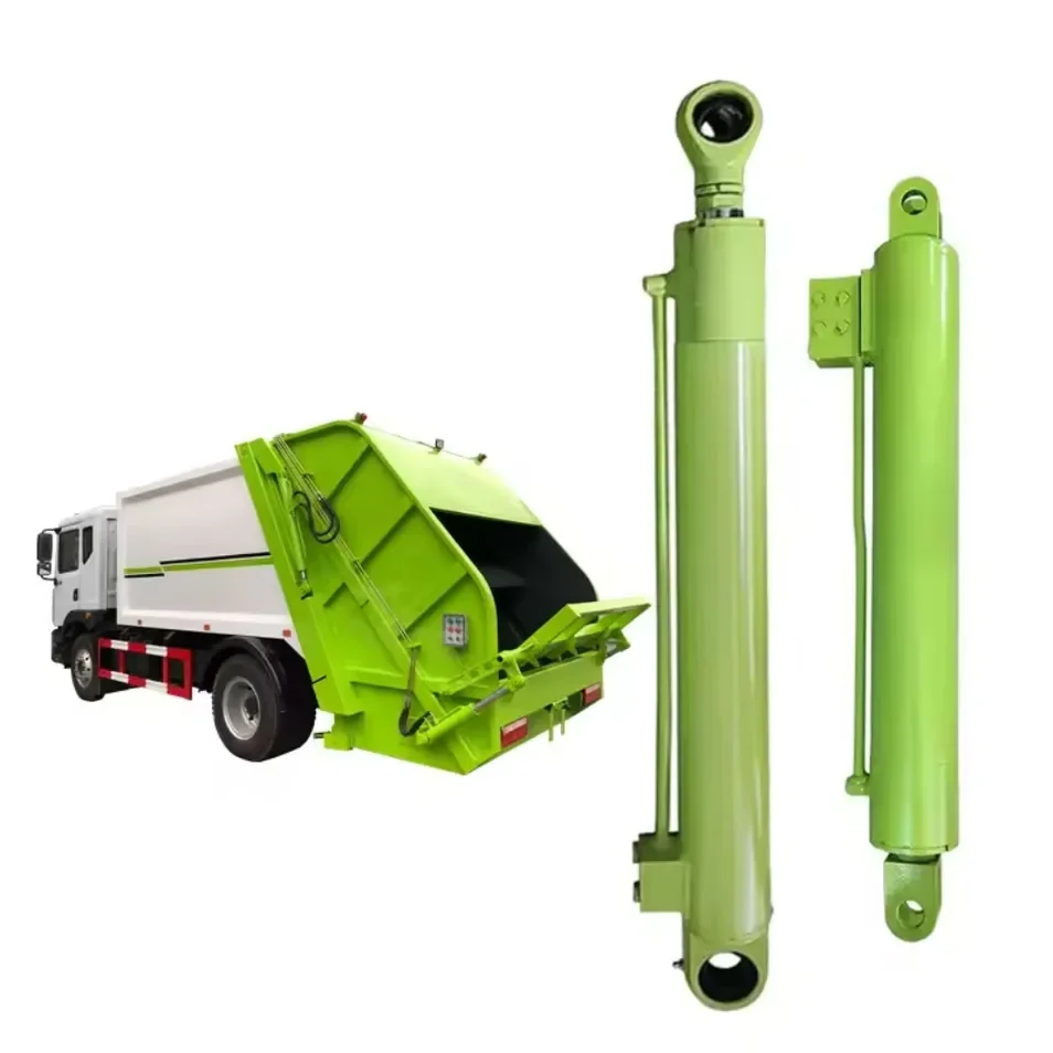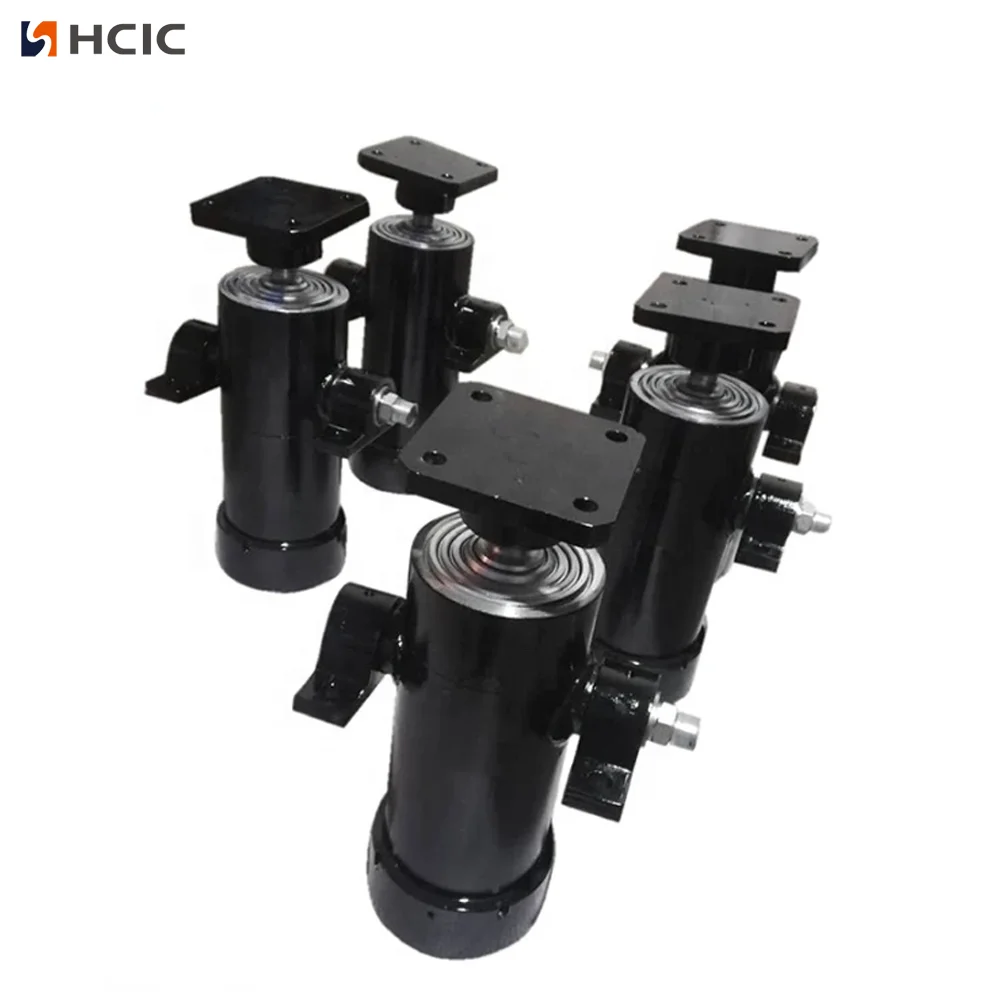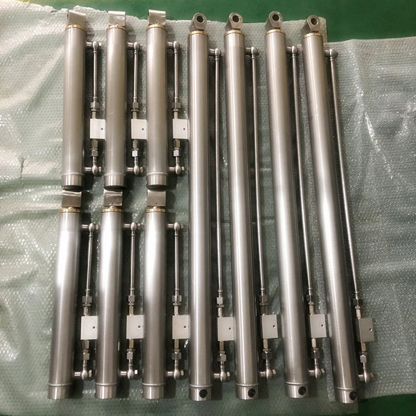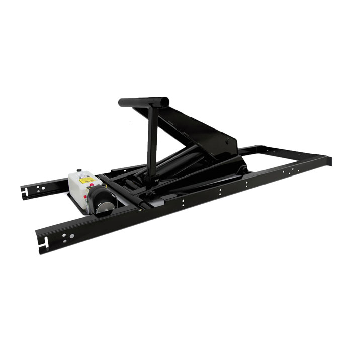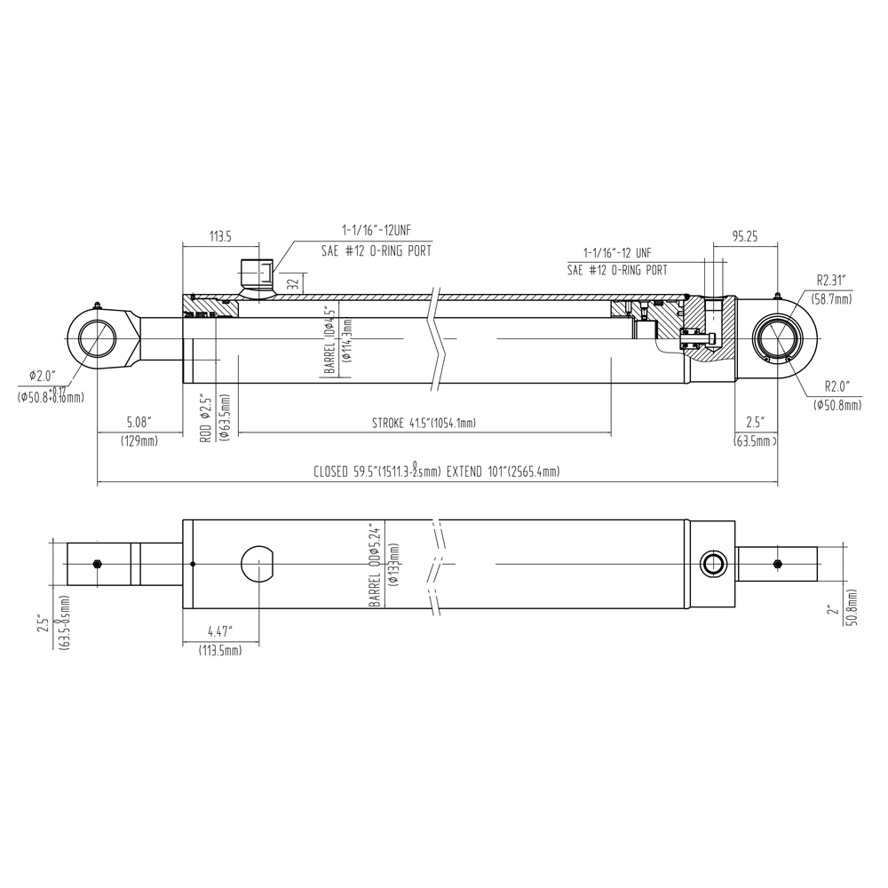

Review the HCIC HR4520 rack gear pivot cylinder listed for tarp systems: 2.5-inch bore, 1.25-inch rod and 16-inch stroke, with fitment checks for pivot geometry and hose routing.
Bore:
2.5 inRod diameter:
1.25 inStroke:
16inThe HR4520 is a rack gear pivot cylinder listed in the HCIC-2026 product catalog for a hydraulic tarp-system application. Its catalog dimensions are:
The cylinder is not the complete pivot mechanism. It supplies linear movement, while the rack, gear, pivot shaft, brackets and tarp frame convert that movement into rotation. The fitment review must therefore cover the cylinder and the mechanical transmission together.
The catalog page does not provide a model-specific working pressure, weight, closed length, port size or flow requirement for HR4520. Those values must be confirmed from the proposed circuit and technical drawing.

| Parameter | Catalog value |
|---|---|
| Model | HR4520 |
| Bore | 2.5 in |
| Rod diameter | 1.25 in |
| Stroke | 16 in |
| Application | Rack Gear Pivot Cylinder |
| Product family | Tarp System Hydraulic Cylinder |
|
|
|
The listed dimensions support an initial identification and geometry review. They do not, on their own, approve a replacement or establish the operating limits of the complete tarp system.
A rack gear pivot mechanism uses linear movement to rotate a gear or pivot shaft. In a tarp system, that rotation can move the cover frame between operating positions according to the machine's linkage design.
The cylinder's 16-inch stroke is linear travel. It is not automatically the angle of tarp movement. The resulting rotation depends on rack pitch, gear diameter, pivot position, linkage limits and the point where the cylinder connects to the rack.
This distinction is important when a buyer compares an old cylinder with HR4520. Two cylinders can share the same bore and stroke but produce different machine movement if the rack, gear or mounting bracket changes.
The bore and rod dimensions establish the cylinder's main working geometry. Bore is related to pressure area, while rod diameter affects the rod-side effective area and the physical connection to the rack mechanism.
The 1.25-inch rod also affects the available rod-side area and the hardware used at the rod end. Final force and speed cannot be stated from the catalog row alone because they require the actual system pressure, flow, valve arrangement, mechanical resistance and pivot geometry.
The model should be checked against:
Measure the linear rack movement required to move the tarp frame from the parked position to the operating position. Compare that requirement with the HR4520 catalog stroke of 16 inches.
The measurement should include end clearances. A cylinder that reaches the nominal positions but bottoms out before the mechanism reaches its designed stop can transmit damaging loads into the rod, mount or rack.
Confirm the rack tooth profile, gear diameter, pivot shaft location and available engagement. The cylinder should push the rack along its intended line without forcing the rack sideways or loading the rod laterally.
The catalog identifies the application as a rack gear pivot cylinder but does not publish the rack, gear or bracket dimensions. Those mechanical interface details must be provided by the machine designer or confirmed during the technical review.
Record the mounting centers with the tarp frame in both operating positions. Then check the full path between them. Look for contact with the frame, cover material, body side, brackets, gear housing and hydraulic hose.
A correct stroke is not enough if the cylinder angle changes in a way that creates binding near either end of travel.
4.4 Protect the hose and fittings
Tarp mechanisms move frequently and often operate around dust, moisture, road spray and cargo residue. Hoses should be routed away from the rack teeth, pivot shaft, sharp edges and pinch zones. Provide enough slack for the complete movement without allowing the hose to loop into the mechanism.
Port size and working pressure are not listed for HR4520 in the catalog row. Confirm the actual connection and hose specification for the proposed system rather than assuming it from another tarp cylinder.
The tarp frame and rack should have a defined end-of-travel arrangement. The cylinder should not be used as the only stop unless the machine design specifically allows that condition and the component ratings have been verified.
Inspect the rack, gear, brackets and cylinder mounts for impact marks that indicate repeated hard stopping or misalignment.
Before ordering HR4520, confirm:
This checklist is more reliable than matching only the cylinder's bore and stroke. The rack and gear are load-transfer components; their alignment directly affects the force seen by the actuator.
A useful OEM or replacement inquiry should include:
If the rack and gear are damaged, repair or replacement of the cylinder alone may not solve the problem. Include the complete pivot mechanism in the review.
The HCIC-2026 catalog confirms HR4520 as a 2.5-inch bore, 1.25-inch rod, 16-inch stroke rack gear pivot cylinder for tarp-system use. It does not publish a model-specific working pressure, port size, weight, closed length, force, speed, rack pitch, gear size or universal fitment guarantee.
No material, coating, certification, service-life, customer result or delivery claim is added beyond the catalog information. Those facts must be confirmed from the technical drawing and the actual application.
HR4520 is a focused hydraulic actuator for rack gear pivot mechanisms in tarp systems. Its catalog identity is clear: 2.5-inch bore, 1.25-inch rod, 16-inch stroke and rack gear pivot application.

The correct selection depends on more than those three dimensions. Share the rack geometry, pivot arrangement, mounting centers and hydraulic circuit with HCIC so the proposed cylinder can be assessed as part of the complete tarp system.
HCIC, also known as Jinan Huachen Industrial Co., Ltd., manufactures hydraulic cylinders, hydraulic power units and hydraulic components for vehicle, trailer and industrial equipment. Final suitability should be confirmed against the actual machine design and operating conditions.