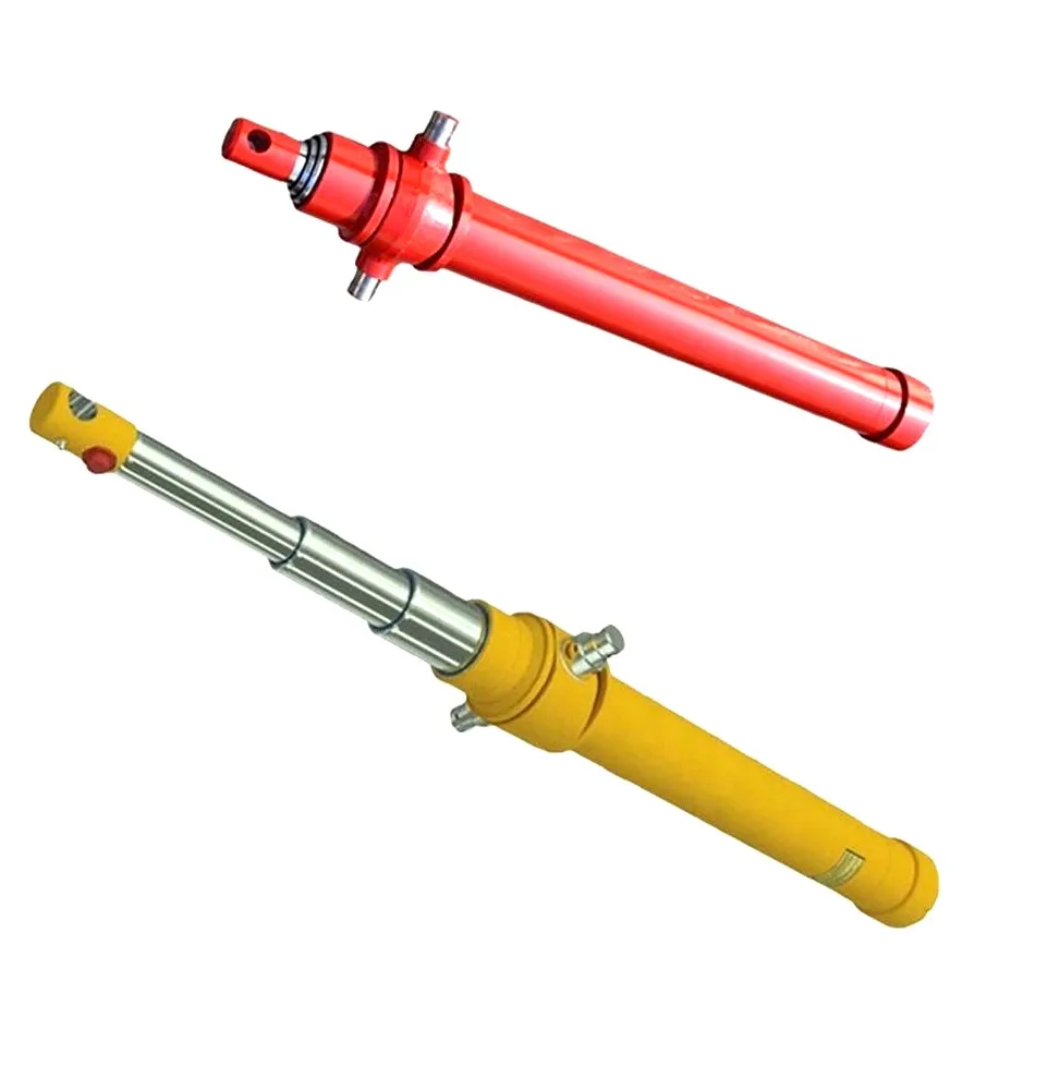
When an OEM engineer asks for a hydraulic cylinder that can “push 10 tons” or “pull 10 tons,” the first question is whether that force is required on the full-bore side or the rod side. A differential hydraulic cylinder has a full piston area on one side and an annular area on the other. The rod occupies part of the rod-side area, so the available pull force is lower at the same pressure.
That difference is easy to miss when a replacement cylinder is selected by outside diameter or an old part number. It is also why a cylinder that appears to have enough nominal capacity may not deliver the required force in the actual direction of motion.
This guide explains the calculation logic used for an initial OEM review. It is not a substitute for a complete machine design, structural check, hydraulic-circuit review or safety assessment.
The bore, or piston diameter, determines the full piston area exposed to pressure. A larger bore can produce more theoretical force at the same pressure, but it also changes oil volume, required flow for a given speed, cylinder envelope and mounting requirements.
Rod diameter affects pull force because the rod occupies area on the rod side. It also affects the rod connection, guide loading, available clearance and the way the cylinder handles compression or tension. A rod cannot be selected from pull force alone; stroke, mounting, guidance and the actual load path also matter.
Use the pressure that is actually available at the cylinder during the required movement, not only the pump's maximum relief setting. Pressure losses through valves, hoses, fittings and other components can reduce the pressure delivered to the cylinder. The machine's operating sequence should determine the design pressure used for the first calculation.
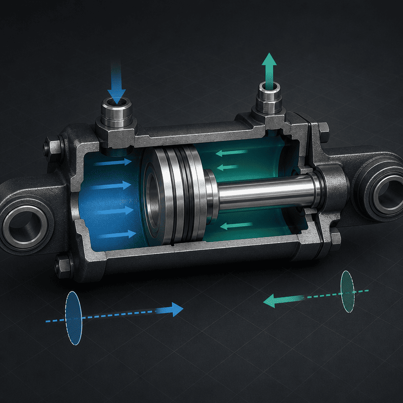
For a first-pass calculation using consistent units:
Push force:
Pull force:
Where:
For a circular section:
If pressure is entered in psi and diameter in inches, the result is in pounds-force. If pressure is entered in pascals and diameter in metres, the result is in newtons. Keep the unit system consistent from start to finish.
These equations describe theoretical hydraulic force. They do not automatically include seal friction, guide friction, mechanical losses, pressure drop, load angle, acceleration, structural deflection or a safety factor.
Assume an engineer is screening a cylinder with:
The full piston area is:
The rod area is:
The first-pass theoretical values are therefore:
The difference is not a manufacturing defect. It comes from the rod displacing area on the rod side. The example is for calculation training only; it is not a rating for a specific HCIC product or machine.
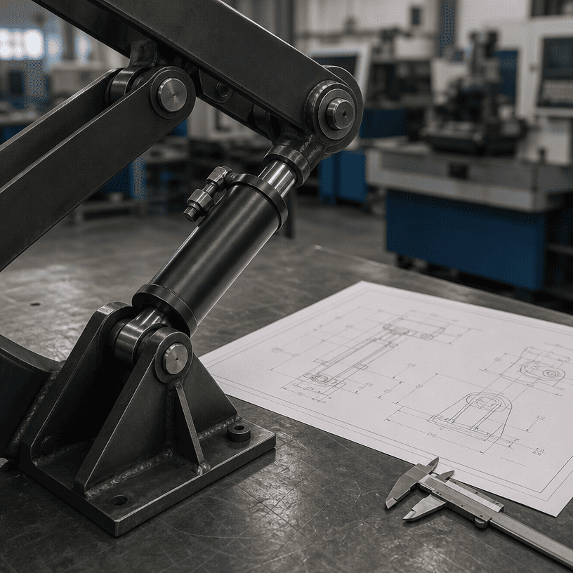
The load does not always act directly along the cylinder centerline. A lever, linkage, hinge or scissor arrangement can increase or reduce the force required at different positions. The engineer should calculate the worst point in the movement, not only the starting position.
The angle between the cylinder and the driven member also matters. A cylinder may have a high theoretical force but a poor force component at a particular angle. A drawing showing the load path and positions is more useful than a single load number.
Breaking a load free, accelerating it and moving it at steady speed are different conditions. Seal friction, guide resistance, inertia and material resistance can make the initial force higher than the force required during a smooth part of the stroke.
For equipment such as ejectors, compactors, grabs and lifting mechanisms, the buyer should describe when the highest force occurs and whether the load can jam or change during the stroke.
The pressure reading near the pump may not be the pressure at the cylinder port. Hose length, fittings, directional valves, flow controls and back pressure all influence the available pressure. A reliable calculation should identify where the pressure is measured and under which operating condition.
A rod loaded in compression may require a rod-stability review, especially in a long-stroke or poorly guided arrangement. A rod loaded in tension may be controlled by different connection and material limits. This article does not replace a buckling calculation or structural verification; it separates force-area calculation from those additional checks.
A larger bore can increase force, but it also increases the oil volume required to move the piston through a given stroke. For a target speed, the required flow is related to the effective chamber area and piston velocity. The rod side has a different volume per unit length from the full-bore side.
That creates a design trade-off:
A cylinder should therefore be sized with the pump, valve, reservoir, hose, mounting and machine cycle as one system.
A useful OEM inquiry should include:
The more complete the load path, the easier it is to distinguish a cylinder-sizing problem from a structure, linkage or hydraulic-circuit problem.
Hydraulic cylinder push and pull force calculation starts with three basic inputs: bore diameter, rod diameter and effective pressure. The full piston area determines the first-pass push force, while the rod reduces the effective area and therefore the pull force.
That calculation is only the beginning. Linkage angle, starting resistance, speed, pressure loss, rod loading, mounting, guidance and machine structure determine whether a cylinder is suitable for the real application. OEM buyers who provide the complete load path and hydraulic data can receive a more useful quotation than buyers who submit only a force number.
HCIC develops and manufactures hydraulic cylinders, hydraulic power units and related components for vehicle, waste-handling, construction and industrial equipment. Technical suitability should be reviewed against the actual machine design and applicable safety requirements.