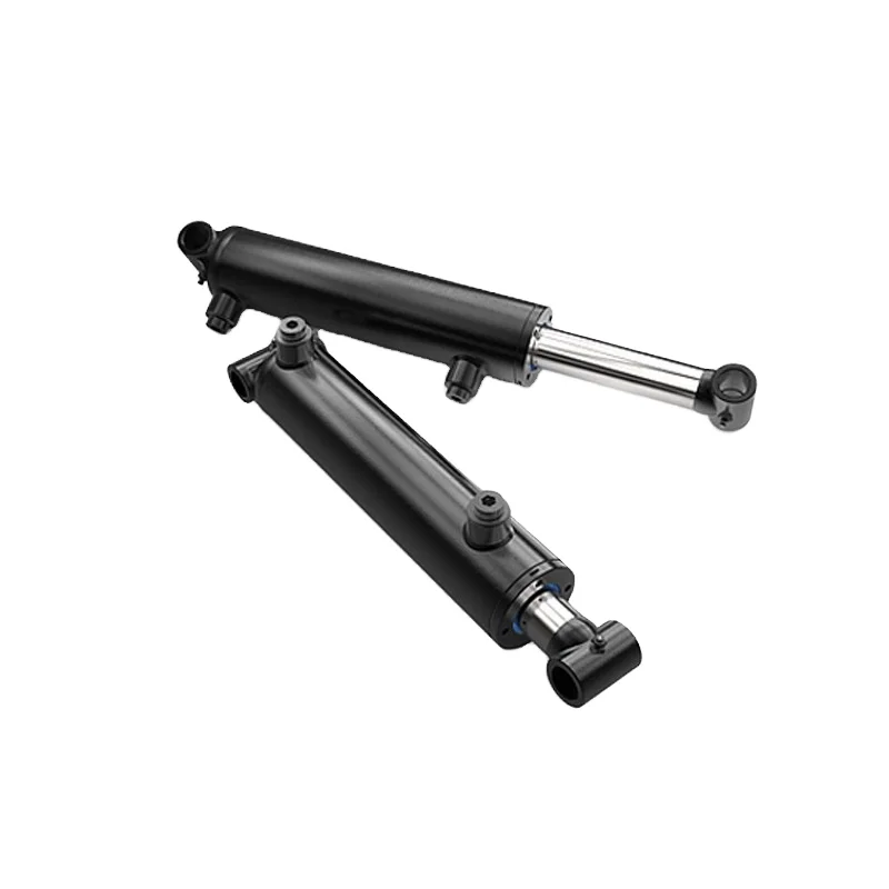
A hydraulic cylinder can develop unstable movement, uneven loading or repeated seal damage even when the hydraulic circuit appears normal. The cause may be in the mounting hardware: a worn pin, an enlarged clevis hole, a loose bushing or an installation that is no longer aligned through the full working arc.
This guide explains how maintenance teams and OEM buyers can inspect the cylinder mounting points before ordering a repair kit or replacement cylinder. The focus is the mechanical connection between the cylinder and the machine, not a general hydraulic pressure or flow diagnosis.
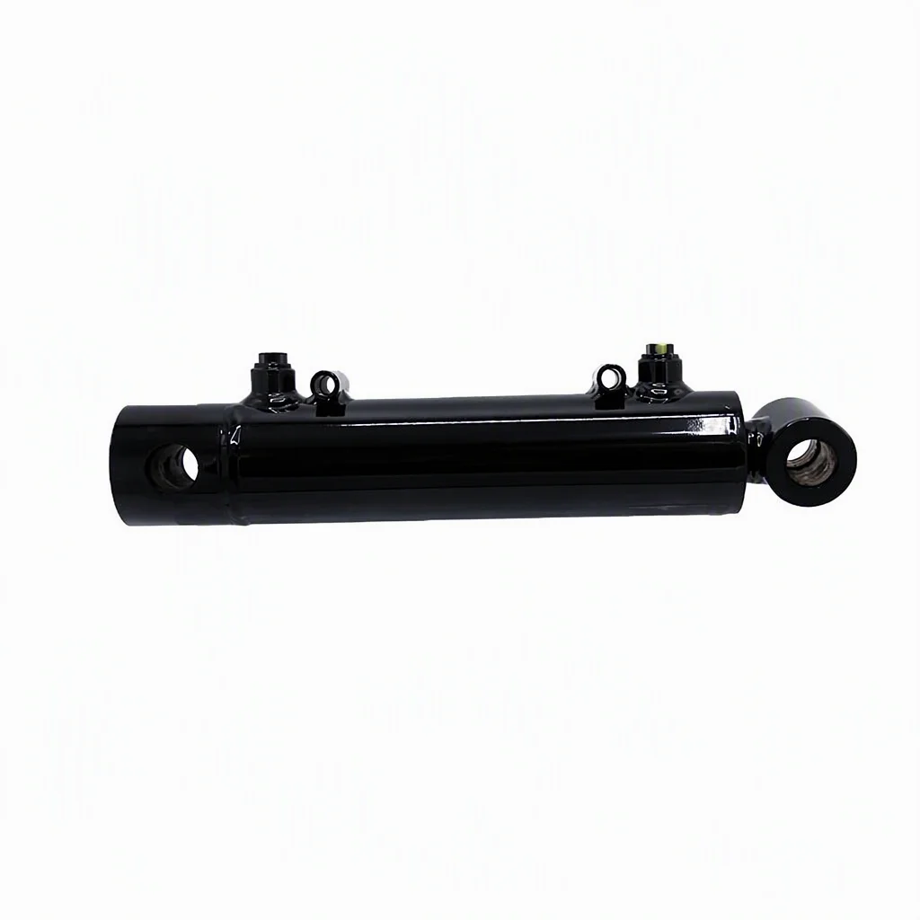
A cylinder does not work in isolation. Its rod and barrel are connected to the machine through pins, clevises, lugs, trunnions, brackets or other mounting features. These parts transfer the working force while allowing the cylinder to move through its designed arc.
When the connection wears, the cylinder may no longer remain on the intended centerline. The machine can then place additional movement and contact on the rod, gland, guide, tube or mounting bracket. A new seal or a new cylinder may not solve the problem if the worn machine-side connection remains in service.
Parker's cylinder safety guide states that the rod and its mating machine component should be checked for proper alignment in both extended and retracted positions. It also recommends that clevis-mounted cylinders pivot at both ends with the pin centerlines parallel and that the cylinder be checked through its working arc for interference. These are installation and safety principles; the final limits must come from the cylinder and machine manufacturer.
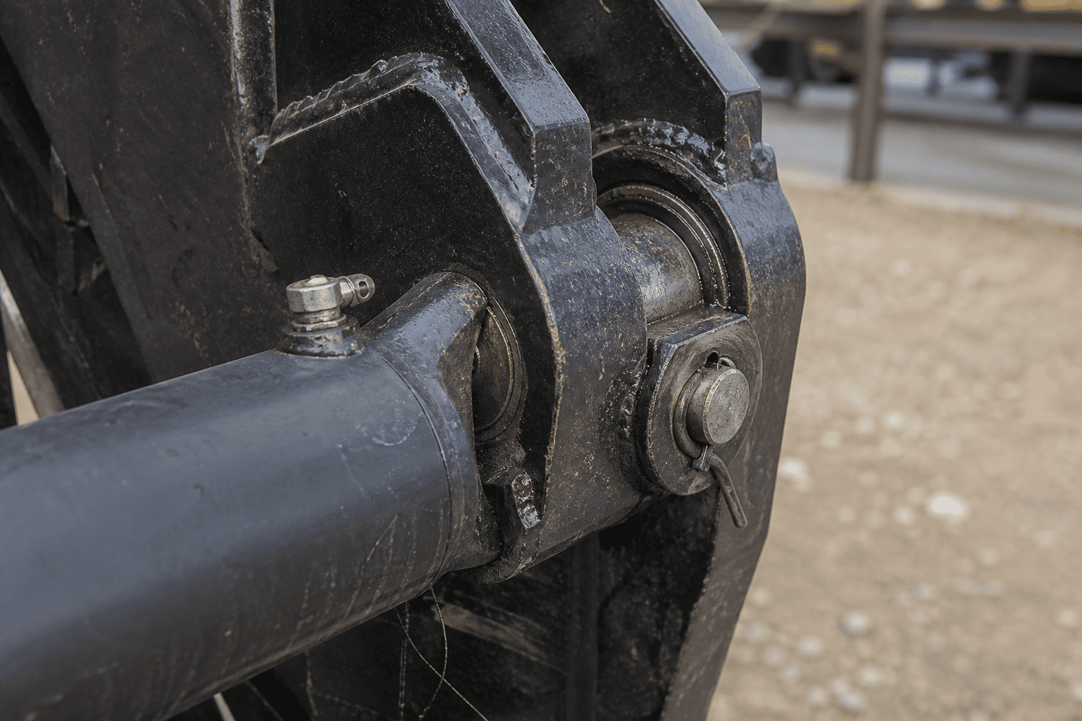
Inspect the pin for scoring, grooves, corrosion, flat spots and a wear band concentrated on one side. A pin that no longer has a round, stable bearing surface can allow the cylinder eye to move before the machine member responds.
Do not judge the pin only by whether it can still be removed. A pin may remain in place while its working surface, retaining feature or fit with the bushing has already deteriorated.
A bushing can wear internally, loosen in its housing or become damaged during installation. Check for movement between the bushing and the cylinder eye or bracket, not only movement between the pin and bushing.
If the bushing is a maintenance-free type, follow the equipment manufacturer's installation instructions. Do not add grease or alter the surface treatment unless the specified design permits it.
The cylinder eye or clevis can become enlarged, tapered or oval after prolonged movement with a loose pin. This is often called an egg-shaped hole. Replacing only the pin may reduce the visible play temporarily while leaving the load path misaligned.
Measure the hole in more than one direction and at more than one location. A visual round shape is not enough evidence for a critical repair decision.
A missing washer, loose retainer, damaged snap ring, worn keeper plate or distorted bracket can allow the pin to walk sideways. Check the full retention arrangement and the condition of the bracket faces that control lateral position.
A replacement cylinder should not be installed into a bracket that cannot hold the pin in its designed position.
The following sequence is a field-planning guide. The machine builder's lockout, blocking and stored-energy procedures take priority.
Isolate hydraulic energy, secure the raised or suspended structure with an appropriate mechanical support, and prevent unexpected movement. A hydraulic cylinder must not be treated as the only support for a lifted load during inspection.
Before disassembly, note when the problem appears:
The symptom helps separate a mounting problem from a purely hydraulic control problem, although it does not replace measurement.
Look for displaced retainers, polished contact bands, fretting marks, rust dust, cracked welds, bracket movement and a pin that is no longer centered. Mark the relative position of the pin, washer and bracket if movement is suspected.
Do not use a finger to check a pinch point or place hands between a cylinder eye and clevis.
After the machine is secured, remove the pin according to the equipment procedure. Clean the pin, bushing, cylinder eye and bracket surfaces with a method compatible with the component materials and site rules.
Keep the removed parts together and identify their original location. A pin from one end of a cylinder should not be mixed with a pin from another position before inspection records are complete.
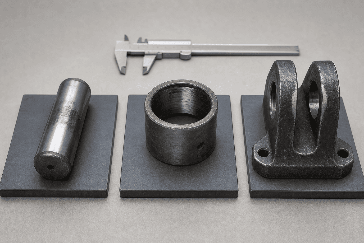
Record the nominal pin diameter, actual pin diameter at several points, bushing inside diameter, bushing outside diameter where relevant, and the condition of the cylinder eye and clevis hole.
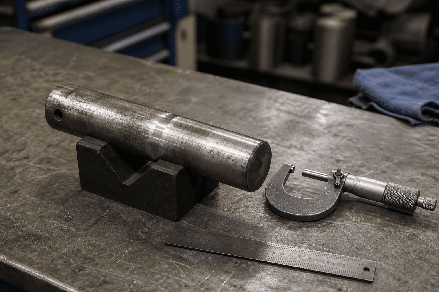
Also check:
Do not invent a universal wear limit. Use the equipment drawing, cylinder manufacturer's specification or an approved repair standard for the final accept/reject decision.
Recheck the machine geometry at the retracted and extended positions, or at the actual end positions allowed by the safe maintenance procedure. The cylinder should not be forced into position by pulling, prying or pressurizing it.
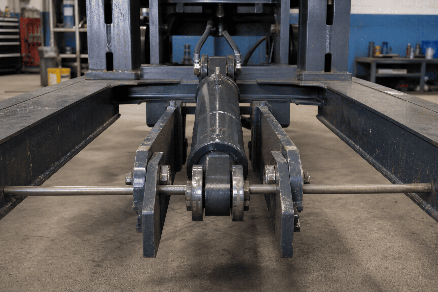
Confirm that the two mounting pin centerlines remain parallel where the mounting design requires parallel pivoting. Check for contact with brackets, guards, hoses, frame members and other moving parts.
| # | Observation | Likely Cause / Indication |
|---|---|---|
| 1 | Pin has a polished band on one side | Uneven contact, alignment change or bracket movement |
| 2 | Pin is smaller at the working zone | Pin wear, inadequate retention or movement under load |
| 3 | Bushing rotates in its housing | Loose fit, damaged housing or incorrect installation |
| 4 | Clevis hole is oval or tapered | Continued operation with clearance or a loose pin |
| 5 | Rust dust or fine metallic debris is present | Fretting, corrosion, insufficient protection or relative movement |
| 6 | Retainer is bent or repeatedly loosens | Pin walk, bracket movement or incorrect retention arrangement |
| 7 | Rod guide or gland shows one-sided wear | Check machine alignment and mounting geometry before replacing seals |
| 8 | Wear appears only near one end of stroke | End-position geometry, interference or changing load path |
These observations are starting points for inspection, not automatic diagnoses. A worn pin can be an effect of a larger alignment problem rather than the original cause.
A pin-only repair may be appropriate when the pin is worn but the bushing, eye, clevis, bracket and retention system remain within the approved dimensional limits. The new pin must match the correct diameter, length, material and retention arrangement.
A bushing replacement requires the correct fit, orientation and installation method. Confirm whether the replacement bushing is lubricated, dry-running or designed for a specific surface condition. Pressing a bushing into a damaged or misaligned housing can reproduce the original problem.
An oval cylinder eye or clevis hole may require an approved repair method such as machining, a repair sleeve or replacement of the affected component. Do not weld, bore or modify a load-bearing mounting feature without engineering approval and a documented repair procedure.
If the cylinder eye, clevis, trunnion or mounting block is cracked, permanently deformed or outside the approved dimensional limits, a replacement cylinder or engineered repair may be necessary. The replacement must be matched to the machine geometry, not selected only by bore or stroke.
A mounting-wear inquiry is much easier to review when it includes actual installation data. Send:
For pin-to-pin cylinders, the closed and extended pin-center dimensions are especially important. A replacement that matches the hydraulic connection but changes the mounting geometry can create a new interference or alignment problem.
Before returning the machine to normal operation:
1. Confirm that the pin and bushing are the specified parts for the mounting.
2. Verify that the pin is fully seated and correctly retained.
3. Check that the cylinder pivots without binding at both ends.
4. Confirm that the rod and machine member remain aligned through the permitted stroke.
5. Check hose routing and port clearance during movement.
6. Operate the machine at low risk and low speed according to the equipment procedure.
7. Stop if the cylinder binds, the bracket shifts, the pin walks or the rod contacts nearby parts.
8. Record the final measurements and repair parts for future maintenance.
Parker's safety guidance also emphasizes that improper alignment can result in excessive rod gland and cylinder bore wear. This is why the installation check should be completed after the repair, not only before the old parts are removed.
A controlled mounting inspection can help prevent several expensive repeat failures:
The objective is not to replace every worn part automatically. It is to identify the actual load path and restore the mounting geometry that the cylinder was designed to follow.
HCIC can review replacement and custom hydraulic cylinder requirements from the real installation data: mounting dimensions, pin arrangement, stroke, bore and rod information, port configuration, application and available drawings. For worn mounting points, include photos and measurements of the machine-side brackets so the quotation review covers fitment as well as hydraulic connection.
Hydraulic cylinder mounting pin and bushing wear is a mechanical fitment problem that can become a hydraulic reliability problem. Inspect the pin, bushing, cylinder eye, clevis, retention hardware and full working arc together. Record measurements before ordering parts, and do not use a new cylinder to compensate for a damaged or misaligned machine structure.
If you need an OEM replacement or a custom pin-to-pin hydraulic cylinder, send HCIC the old-cylinder dimensions, closed and extended pin-center distances, pin and clevis measurements, port information, photos and application details. A complete data package gives the engineering team a better basis for confirming fitment before production.