When a hydraulic cylinder moves a multi‑ton mechanism at speeds above 0.1 to 0.2 m/s (4 to 8 in/s), bringing that mass to an abrupt dead stop against the cylinder end cap generates enormous destructive shock.
Many equipment designers assume that setting the main system relief valve to 3,000 psi protects the entire actuator. In reality, once the piston passes the primary exit port and enters the cushion zone, the trapped oil has only one tiny escape route: a calibrated needle valve or precision orifice.
If the cushion geometry is undersized or improperly adjusted, the trapped deceleration pressure behind the cushion spear can easily spike to 6,000 to 10,000+ psi (400 to 700 bar) for a few milliseconds.
Over thousands of cycles, these violent pressure transients lead to:
An internal hydraulic cushion converts the kinetic energy of the moving mass (plus the continuous propelling force from the pump) into heat by forcing a trapped volume of oil through a restricted orifice over a short deceleration stroke sc (typically 20 to 40 mm or 0.75 to 1.5 in).
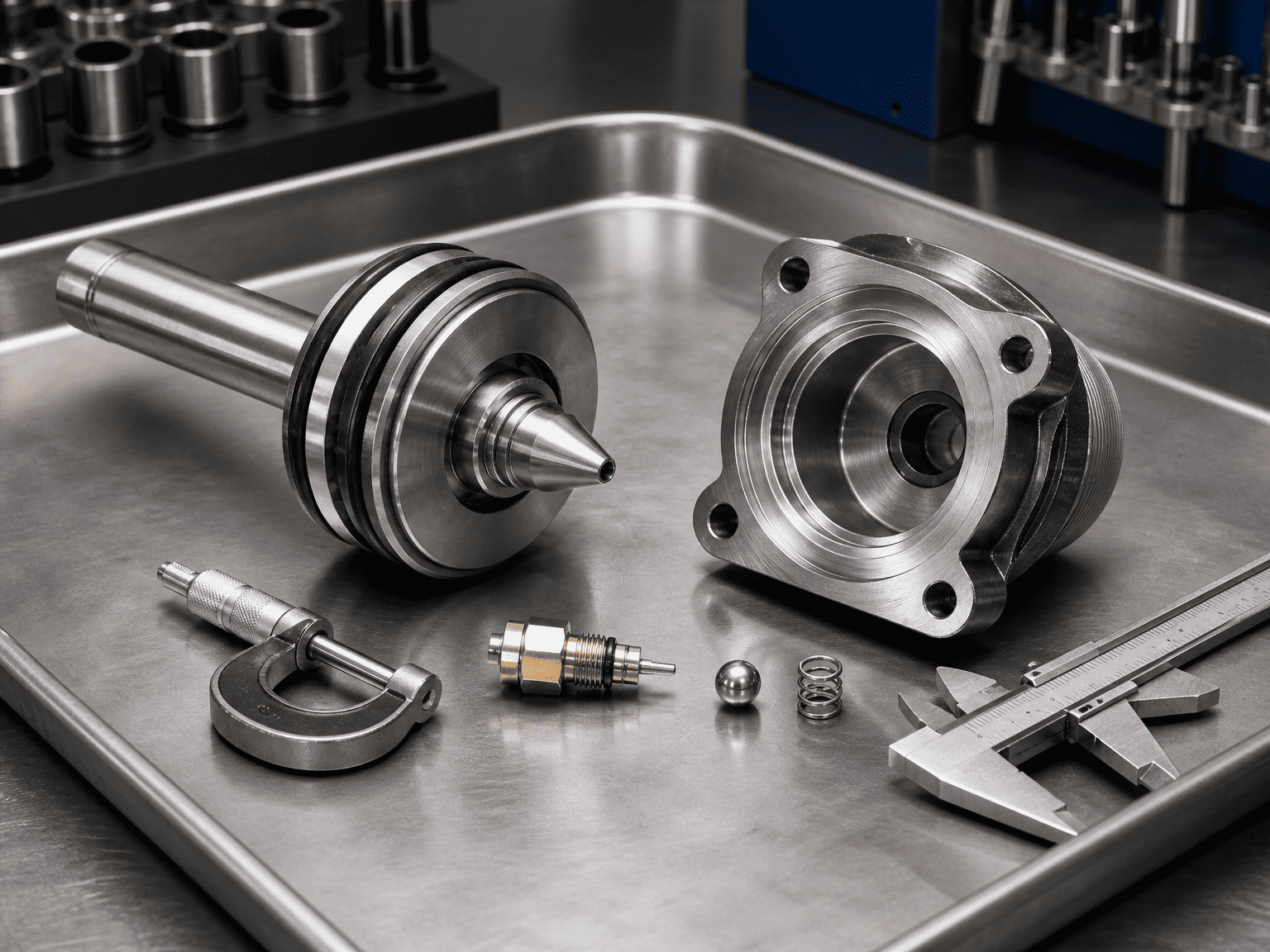
A properly designed cushion assembly includes three core mechanical elements:
Step‑by‑Step Cushion Energy & Pressure CalculationTo determine whether an internal cushion can safely handle your load without exceeding the cylinder's burst or fatigue threshold, calculate the total energy to be absorbed:
Ek = ½ m v²
Where:
m = Total moving mass (including piston, rod, attachments, and external payload in kg or lb)
v = Maximum velocity at the moment the cushion spear engages the cavity (m/s or in/s)
If pump flow continues during deceleration, the system pressure continues pushing the piston across the cushion stroke sc:
Wprop = Fprop × sc = (Psys × Apiston) × sc
Where:
Psys = Driving system pressure (Pa or psi)
Apiston = Effective area of the driving side (m² or in²)
sc = Effective length of the cushion spear (m or in)
Etotal = Ek + Wprop ± Wgravity
(Add or subtract gravity work m g sc sinθ if moving vertically or on an incline).
The average deceleration force Fdec required is:
Fdec = Etotal / sc
The resulting average hydraulic pressure inside the cushion chamber Pcushion is:
Pcushion = Fdec / Acushion
Where Acushion is the annular area of the trapped oil column in the cushion pocket (Abore − Aspear or Arod).
Engineering Rule of Thumb: Peak transient pressure during initial spear entry typically reaches 1.5 to 2.2× the calculated average cushion pressure. If the calculated peak exceeds 1.5× the cylinder’s maximum rated fatigue pressure, an external proportional deceleration valve or longer custom cushion spear is required.
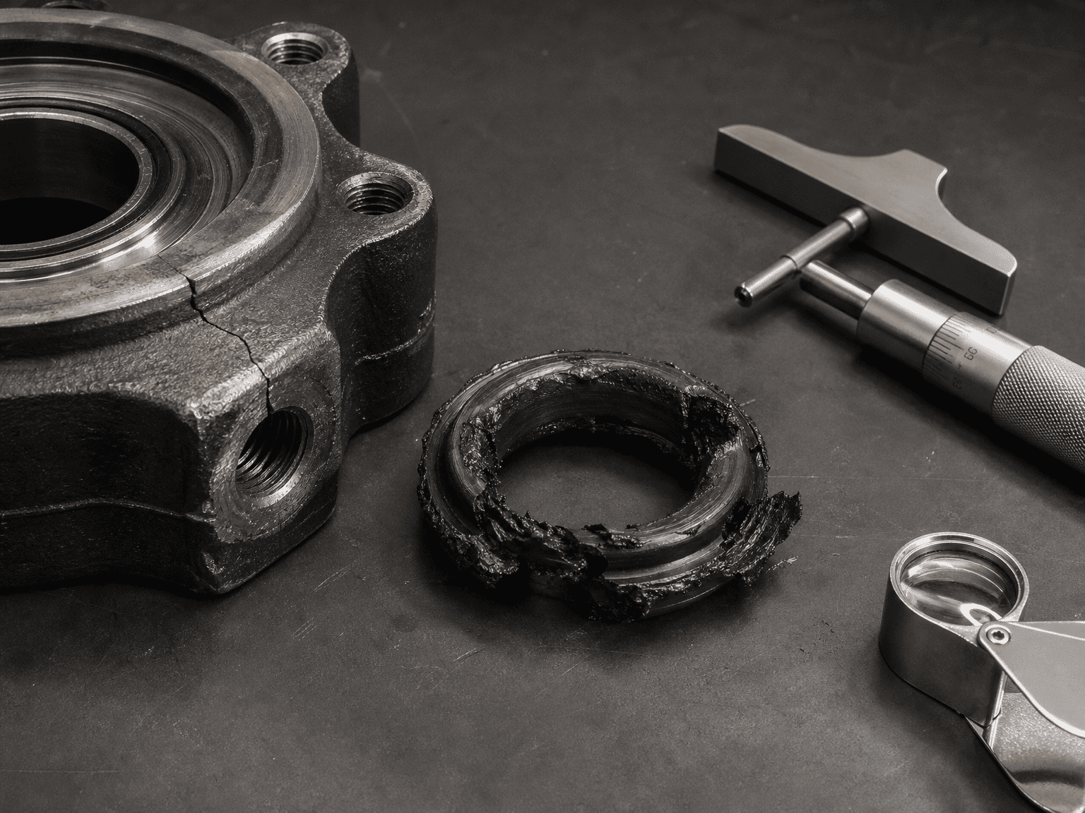
1. Backing the Needle Valve Fully In (Zero Flow): Operators trying to eliminate end-stroke noise sometimes close the needle valve completely. This creates total hydraulic lock in the cushion pocket, forcing oil past the spear clearance and blowing head gland seals.
2. Ignoring Horizontal Inertia on Free-Rolling Carts: Designers calculating only driving pressure and forgetting the kinetic energy of a 10-ton rolling cart. Even at low pressure, high inertia will crush an internal cushion.
3. Using Standard Cushions with Water-Glycol or High-Viscosity Cold Oil: Thicker fluids or low-viscosity fire-resistant fluids significantly alter flow through the metering needle, causing severe over-pressurization during morning winter startups.
4. Neglecting Fluid Deaeration: Spongy, aerated oil entering the cushion compresses like a spring, causing bouncing, dieseling, and erratic deceleration.
When requesting engineered cushioned cylinders from HCIC, provide:
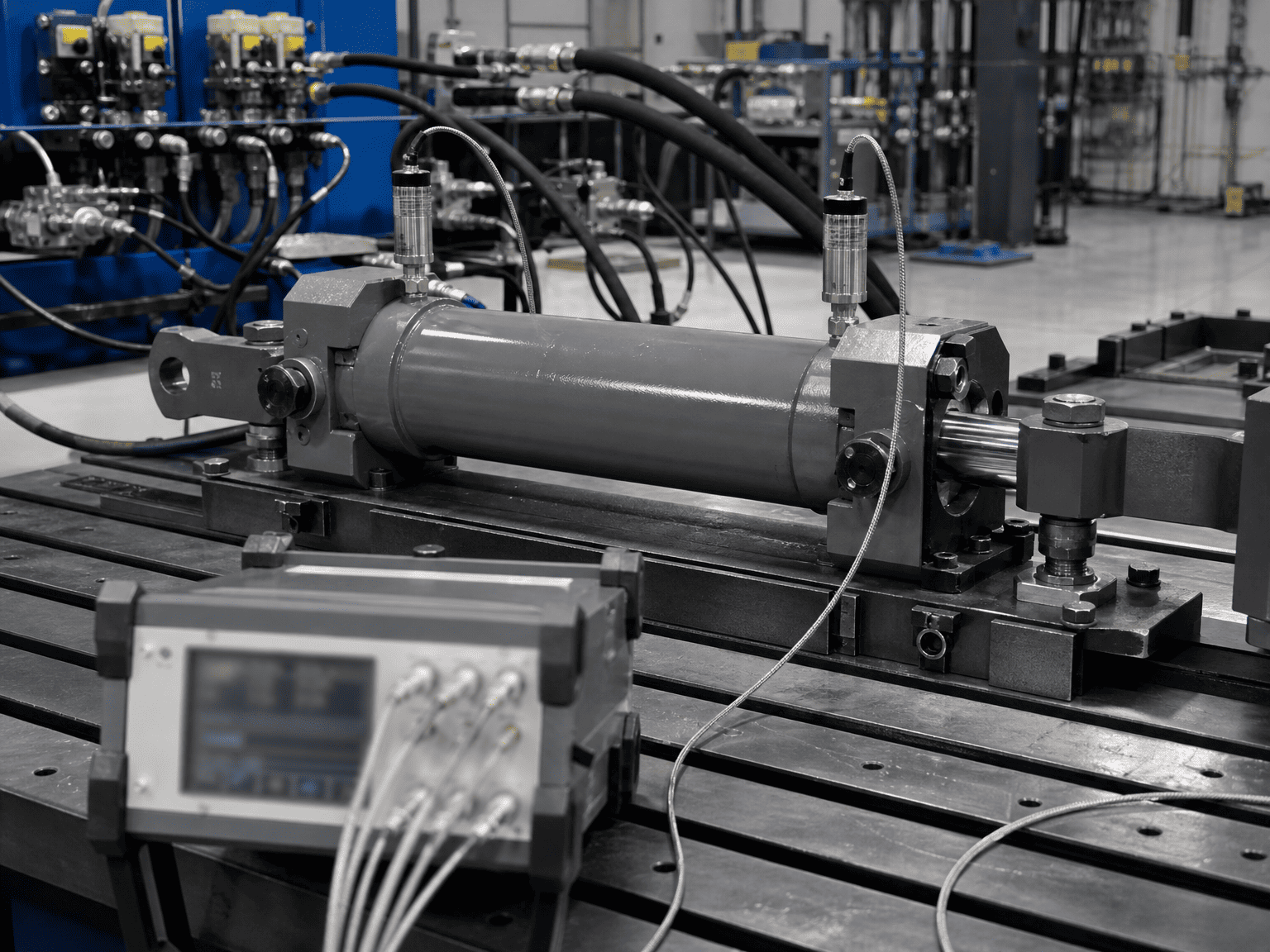
Cushion calculations presented above provide foundational sizing estimates based on rigid-body mechanics. Actual peak dynamic pressures depend on hydraulic oil bulk modulus, line capacitance, needle orifice discharge coefficients, and valve response times. Final equipment designs should be verified through pressure transducer testing and transient simulation.*
HCIC engineers custom industrial and mobile hydraulic cylinders with tailored cushion profiles for high-impact applications worldwide.